Maslow Ring System Sled
Files
Edit this page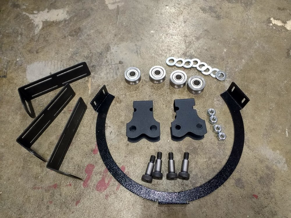 | Download FilesSource |
Maslow Ring System Sled
The design files for the Maslow ring system
Ring OnShape parts:
About the ring system:
The ring system was designed as an improvement over the old chain attachment system which was two L brackets. The L brackets attached the sled at two fixed points which meant that the math relating the lengths of the chains to the position of the sled needed to take into account the sled's rotation which is very complex. It also meant that other forces like the dust collection hose dragging could impact accuracy.
The solution to these issues is to have the chains meet at a single point at the router bit. This makes the router bit the center of rotation and greatly reduces the math required. The issue is that the router bit is already taking up that space.
A number of solutions have been proposed where the chains attach to something which moves in a circle around the router bit and point directly to it...essentially adding a virtual section of chain which meets at the router bit.
The proposed solutions include using large bearings, linkages which when moved move in an arc around the router bit, and this solution where small bearings run along a ring.
The files are free to use with no restrictions on personal or commercial use.
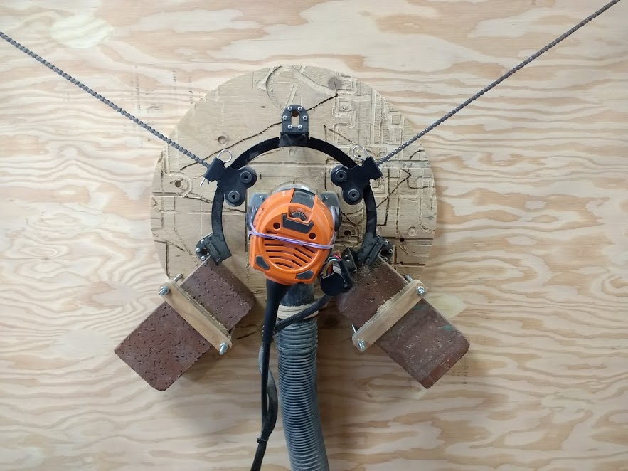
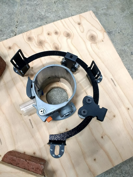
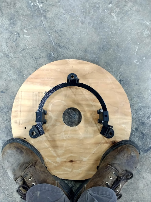
How the ring looks installed:
Instructions
Edit this pageBecause the sled is a shape which could be difficult to make by hand we are going to make a rough version by hand and then use Maslow to cut the final version.
This process is largely the same regardless of which frame design you build, so don't worry if the pictures look a little different than your frame.
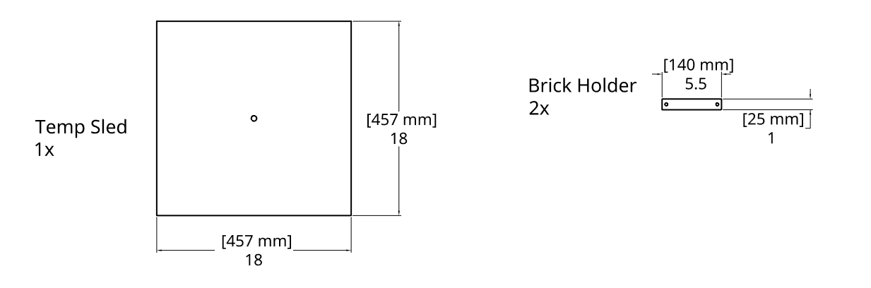
Step 1: Cut plywood parts
If you have not already done so, cut the following shapes from a sheet of plywood. The dimensions of these parts are not critical, and you can cut them by hand.
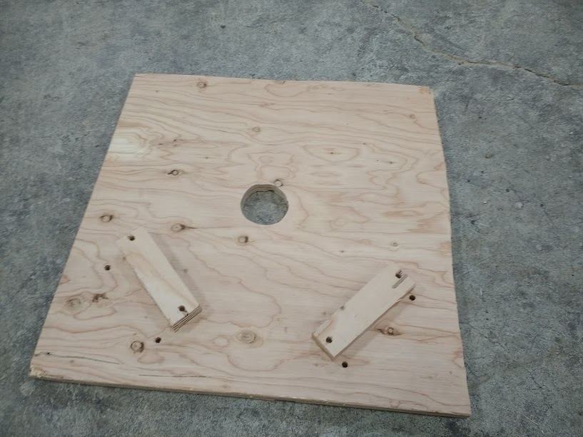
Step 2: Add holes
Next, we need to drill holes in these parts. Adding a hole in the center of the sled will let the router pass through. Adding holes at the bottom of the sled and in the brick holders will let us use bolts to hold the bricks in place.
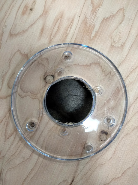
Using your router, route out an approximately 1.5" by 1.5" hole in the center of the sled.
Then place the two brick holders in the lower corners of the sled and drill through them using a 1/4 inch drill bit (7mm).
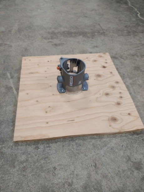
Step 3: Attach router
Attach your router to the sled. This step will vary depending on the router you are using so it's a little bit up to you, but the gist will be the same on most routers.
You will probably need to remove the handles from your router to make it fit within the ring. On the Ridgid router, the handles are held on using two bolts hidden under the caps on the handles. Removing the caps over the bolts can be quite difficult, I ended up drilling a hole in one to get access to the bolt.
Remove the router base plate, and attach the router to the sled using the same bolt holes that the base plate used to attach. The bolts which held the base plate may not be long enough to pass through the plywood.
The base of the router can be used as a template to drill holes for the router mounting bolts.
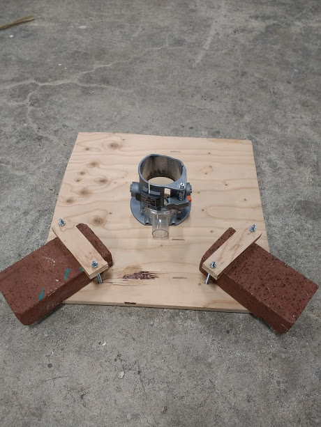
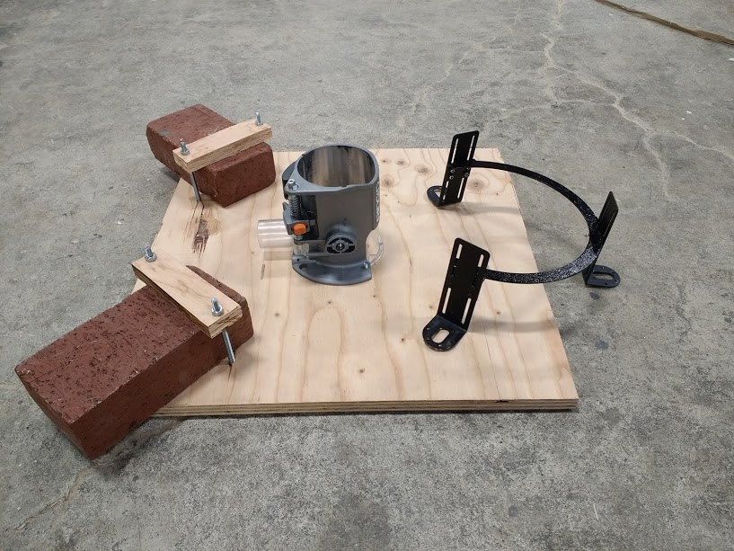
Step 4: Attach the ring and bricks
Attach the two bricks using the bolts and nuts provided and the two wooden brick retainers.
Attach the ring to the sled. The ring attaches using the three adjustable 'L' brackets, the small wood screws, and the small nuts and bolts shown below.
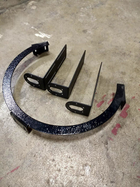
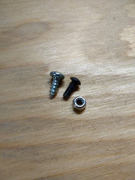
First, attach the 'L' brackets to the ring using the small nuts and bolts, then attach the ring to the sled using the wood screws such that the ring is concentric around the router.
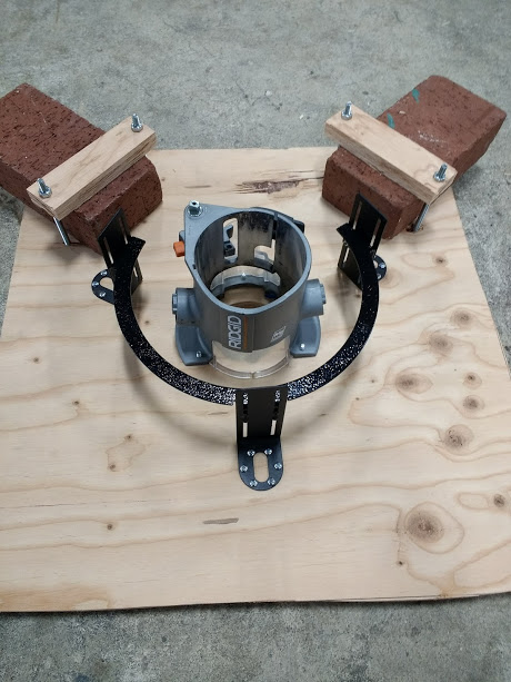
For now do your best to make the ring concentric around the router, on the final sled we will use alignment marks to dial the placement in.
Note that the 'L' brackets are designed to let you move the ring up and down to adjust for your router's center of gravity. When supported by the ring the router should hang vertically. You can move the ring in and out to account for your router's weight distribution.
Step 5: Attach the carriages to the ring
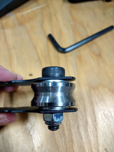
Now we need to assemble and attach the carriages to the ring. To do this we will need the shoulder bolts, bearings, washers, and nuts.
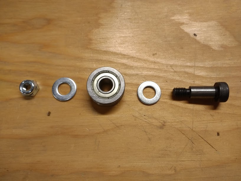
The completed assembly will have the shoulder bolt sandwiching the washers on either side of the bearing. You should be able to tighten the nut down snugly and still have the bearing rotate freely. If the bearing does not rotate freely, check that the shoulder bolt has not become caught on one of the washers.
Assemble one carriage on either side of the ring.
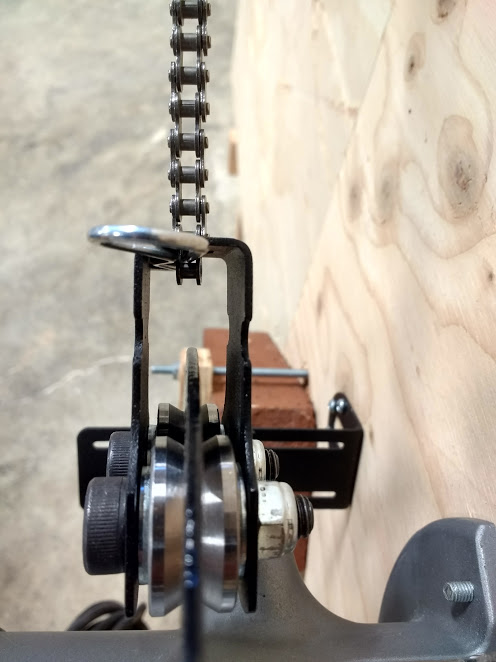
Step 6: Attach sled to frame
Next, we are ready to hang the sled on the machine! To attach the sled to the machine pass the free end of each chain through the hole in the end of each carriage and secure it with a cotter pin. * Please note depending on your chain there may an untrapped end around the last link of chain, in this case it is safest to use a link the is surrounded by another (or go 1 link farther back from the end) to place the cotter pin. Unsurounded links may spread causing the link to fail and the sled to drop suddenly.
Step 7: Calibrate
Now it's time to calibrate the machine. Because each machine is built by hand a calibration step is needed to precisely measure your machine so that it can cut accurately.
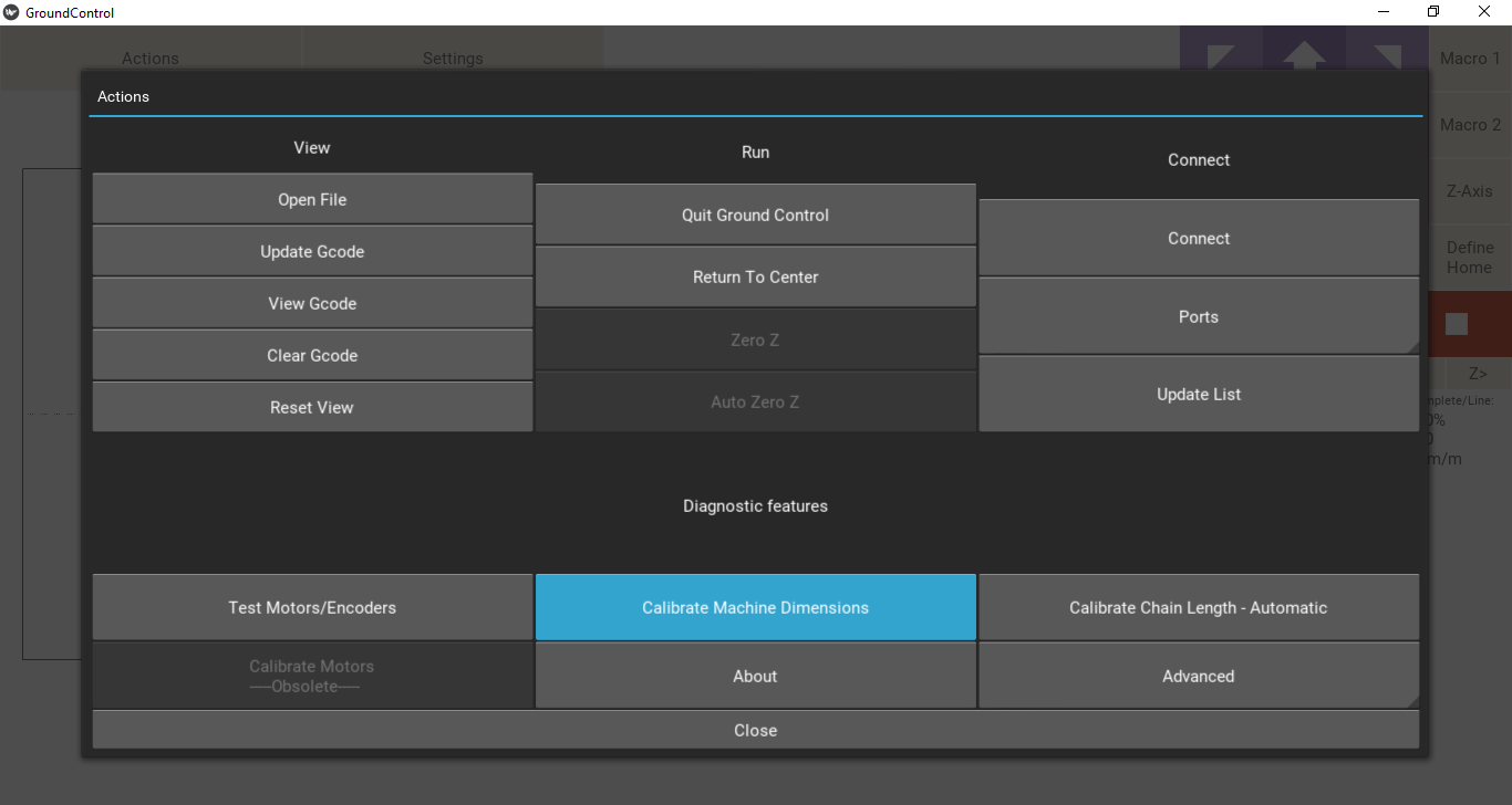
To calibrate the machine launch Ground Control, then click Action -> Calibrate
Step 8: Generate Gcode
Next, we need to generate the gcode file which Maslow will use to cut the parts. The design files for the sled can be downloaded under the "files" tab on this page. If you already have a preferred piece of software to generate gcode files feel free to use it, if not there are step by step instructions to use the free online MakerCAM program here.
A video describing how to use the free online Easel software is available here.

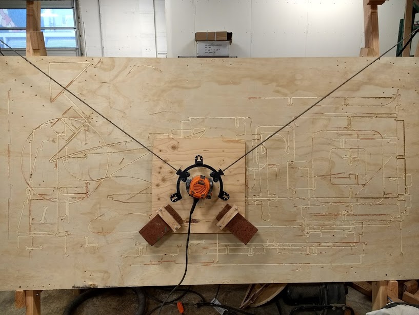
Step 9: Cut the final sled
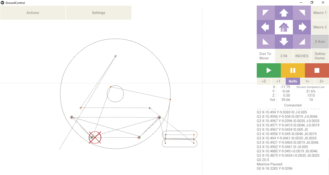
Open the gcode file in Ground Control by clicking Actions -> Open File and then pressing the green start button when you are ready to begin cutting.
Keep in mind that you can move the gcode file around on your 4x8 sheet by moving the router to the desired starting point and pressing the "Define Home" button.
Step 10: Re-attach the hardware
Next, we need to move the hardware from the temporary sled to the newly cut sled. All of the hardware attaches in the same way that it did on the temporary sled.
Note that the final sled has alignment holes to accurately position the ring and that the holes around the bolts for the bricks are countersunk to hide the bolt heads.
Instructions to install the z-axis if you have one can be found here
Step 11: Round over edge
Your sled will slide across the work area much more smoothly with a rounded edge. This can be done using either a round-over bit or some sandpaper.
When your sled is finished re-attach it to the machine and you are ready to start making things!
Note: A quick sanding of the inside edge of the ring can smooth out the protective coating over the metal and help the bearings to move more smoothly