Maslow triangulation linkage kit
Files
Edit this page | Download FilesSource |
Maslow triangulation linkage kit
This is a kit to build a linkage system for a Maslow CNC machine that enables triangular kinematics (as opposed to quadrilateral kinematics) for more accurate cuts and a more stable router sled.
You will receive all of the laser cut parts and all hardware needed to assemble the linkages. Laser cut parts are 1/4" birch plywood and will arrive unsanded and unassembled. The picture above shows an assembled linkage. There is a link for full instructions for assembly and installation at the bottom of this description.
This kit includes brackets for attaching chains!
The wait time varies but kits usually ship within 1 day of placing an order; this timeframe depends on many different factors such as availability of hardware and how many orders I am filling. If the timeline needs to change I will be sure to communicate with you.
If you need your kit sooner than the estimated shipping date I can expedite orders for a small fee. Just contact me and let me know.
Of course if you ever have any problems or questions you can contact me and I will do what I can to help you out!
Assembly instructions can be found here: instructions
More information about this linkage design can be found in the Maslow forums at: forums
Instructions
Edit this pageWhat is a triangulation linkage kit?
A triangulation linkage kit is a physical add-on to your sled that will allow you to change the kinematics in Ground Control from trapezoidal to triangular. There are many advantages to using triangular kinematics, some of which are:
- Improved accuracy
- Extremely simplified computation
- Much easier calibration
- Sled orientation/rotation becomes a non-issue
There are several creative solutions to allow for triangular kinematics, they range from elegant to basic. With the goal of creating an affordable, simple, and accurate solution I have developed a kit that will allow you to convert your Maslow to use triangular kinematics using simple linkages. The linkages mount to the sled around the router and still allow room for Z-axis control and dust collection (using the Ridgid R22002 router). The stock Maslow chains attach to the linkages with the included clevis brackets. All necessary hardware is included. The linkages are laser-cut from high quality baltic birch plywood.
These kits can be ordered at this link
If you would like more information about this concept or if you would like to read some of the development and other ideas around triangular kinematics please see Throwing my hat in the sled modification ring in the forums.
This kit works and has been tested but is still under development, I plan to improve the design and instructions as needed based on further tests and more real-world feedback.
Assembly instructions
Your kit consists of 18 laser-cut wooden parts to make up the 6 linkage bars (bar A through F). Each bar is made up of 3 layers. The layers for each bar are labeled 1, 2, and 3 to denote the order that they should be stacked in. You will also find a small bag of hardware and a small bag of wooden parts.
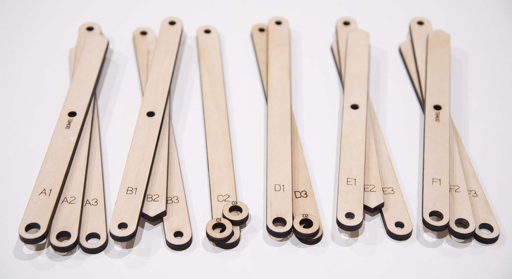
Fig. 1 - These are the 18 parts for the linkage bars
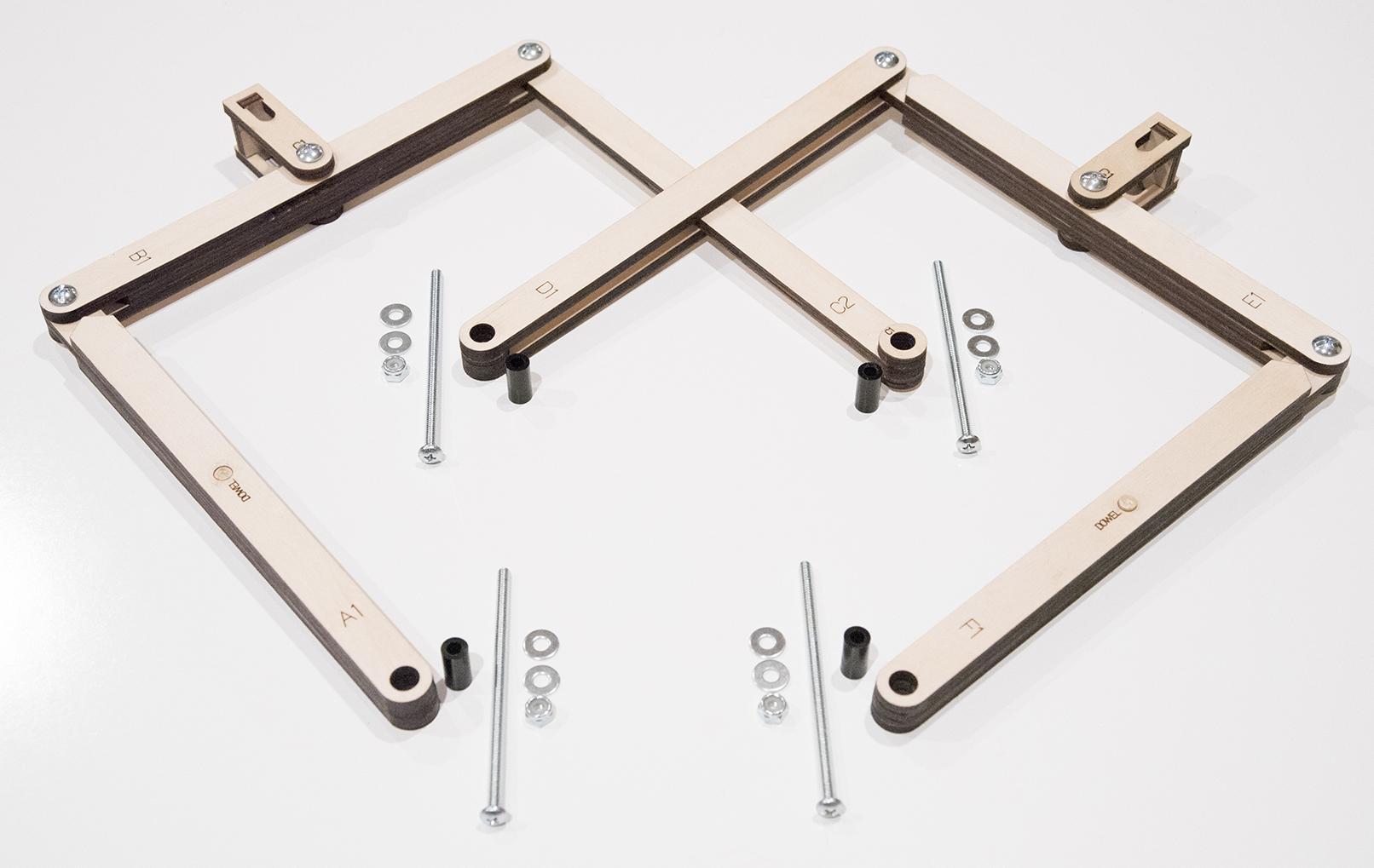
Fig. 2 - A finished linkage with the included hardware, ready to mount
Aside from the 18 wooden parts that glue together to make the 6 linkage bars there will also be 6 smaller wooden parts in a small plastic bag labelled G1, G2, and G3 that make up the clevises.
The hardware is all in one small bag. There will be:
* 4x 1/4" female barrel bolts 1/2" long, #10-24 thread
* 6x 1/4" mating screws with a 1/4" shoulder and #10-24 x 5/16" thread
* 2x 1/4" female barrel bolts 1" long, #10-24 thread
* 4x 4" #10-24 machine screws
* 4x 3/8" OD #10 x 3/4" nylon bushing
* 4x #10-24 nylock nuts
* 4x #10 SAE flat washers
* 2x 3/32" x 1" zinc plated steel cotter pins
Sled preparation
Before you begin assembling your linkage you should mark your sled for accurate placement of the mounting blocks. You can either download and print the paper template: Printable sled drilling template Or you can mark your sled without a printer by using B1 as a compass to ensure you have accurate measurements. Simply divide your sled evenly into 4ths (two lines that cross at 90˚), then with the center hole of B1 at the exact center of the sled mark where the outer holes cross your dividing lines (fig. 3). You will have 4 marks. If you have a sled that already has a large center hole for a router then mount your router to your sled (as you normally would) and chuck a ¼" drill bit (or any ¼" stock) into the router. Extend the drill bit through the sled so it protrudes out the back. Slide the center hole of B1 onto the drill bit and mark your 4 spots as above. Next drill a hole at each mark using a no. 9 or 3/16” drill bit. Take care to avoid any hardware on the top of the sled (like z-axis brackets or router handles).
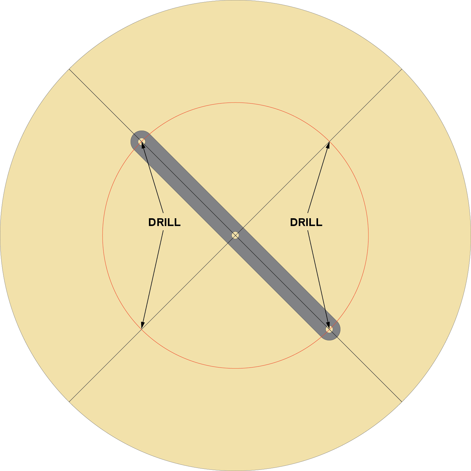
Fig. 3 - Mark and drill 4 holes for mounting the linkage
Linkage Assembly
Begin by sorting the wooden parts into stacks based on their letter (3 A's, 3 B's, etc.) Note: bars C and D also use the small round wooden “washers” that are in the small parts bag. You can ignore all G parts for the moment. Refer to fig. 2 if this gets confusing.
Once they are sorted you can start gluing things together, it doesn’t matter if you go 1-2-3 or 3-2-1 as long as 2 is always in the middle. If you don’t want any of the labels to show in the final product you can face the labels toward layer 2. The etched labels of all three layers should always be on the same end. For instance E1 and E2 are actually identical parts but they are assembled with their labels at the same end (fig. 1)
Sets A and F have a center hole marked “DOWEL”. When you glue these layers together insert one of the provided dowel pins to help align the layers accurately (fig. 5). Make sure all three layers are lined up and gently clamp them until they are dry. Be careful not to apply glue too close to any of the holes (fig. 4) (it’s okay for glue to get in the dowel hole, but that’s the only one). If some glue squeezes into a hole simply wipe it out with a damp Q-tip before it dries.
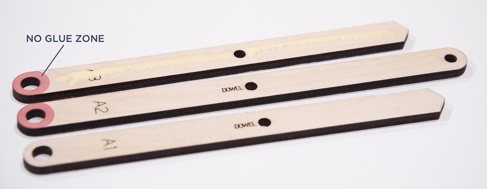
Fig. 4 - The hole marked DOWEL can receive glue but keep glue away from all other holes!
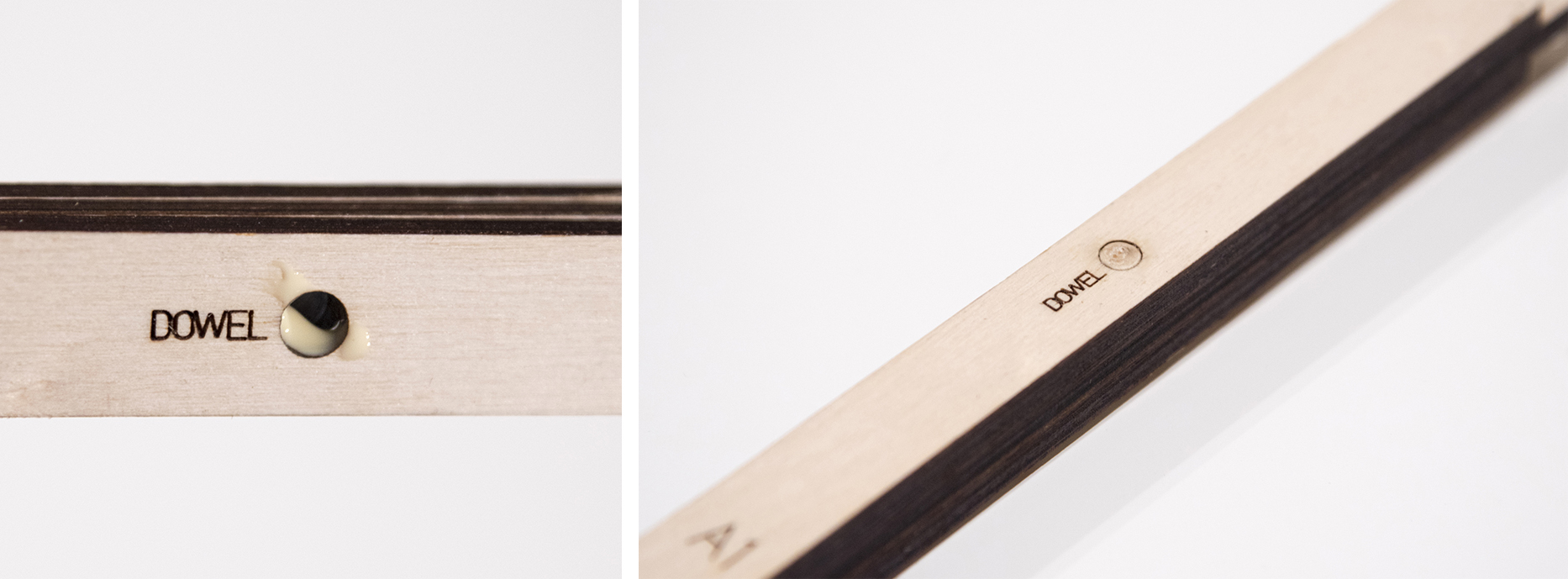
Fig. 5 - Glue a dowel pin into the holes in bar A and bar F. Dowel pins can be trimmed or sanded after the glue dries.
Note, all parts can be sanded before glue-up and the assemblies can be sanded after. Sanding is optional but in some cases might improve use especially where wood surfaces will rub against each other.
Use one of the provided nylon bushings to help align the layers (fig. 6); make sure you don’t accidentally glue a bushing into the hole! Note: bushings may be black or white.
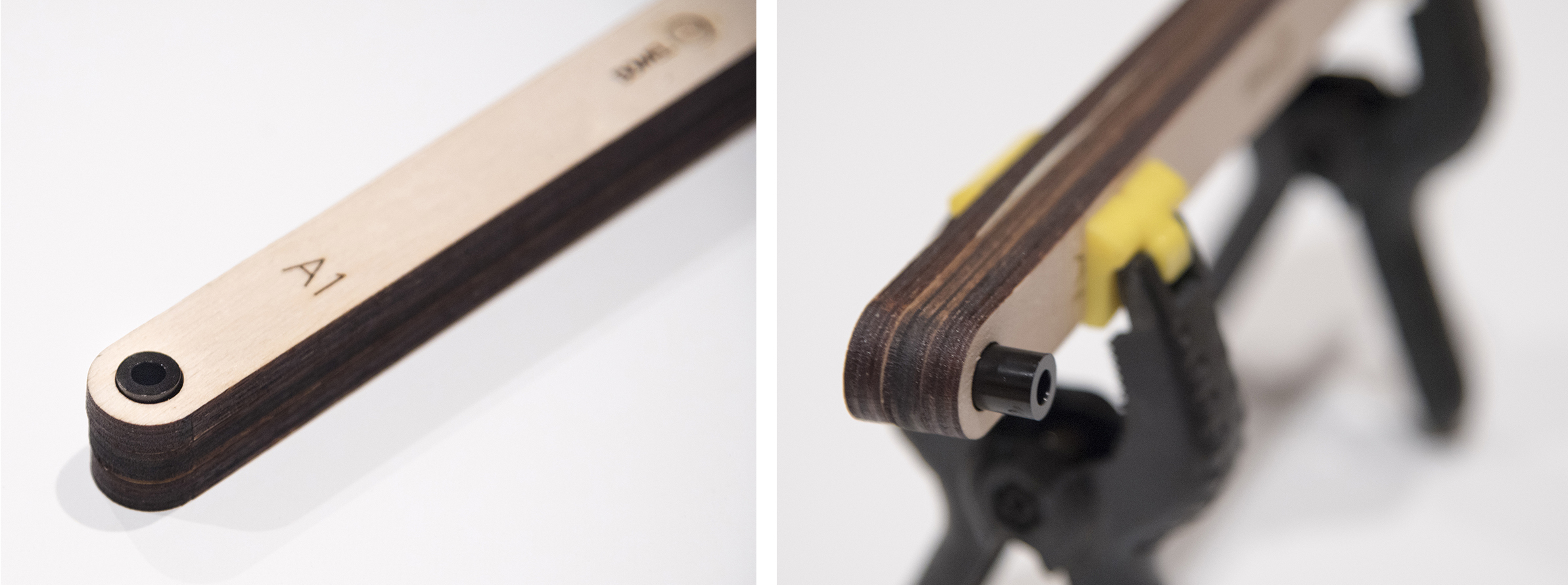
Fig. 6 - Use a nylon bushing to align layers. Periodically move the bushing while the glue dries to assure it doesn’t get glued in.
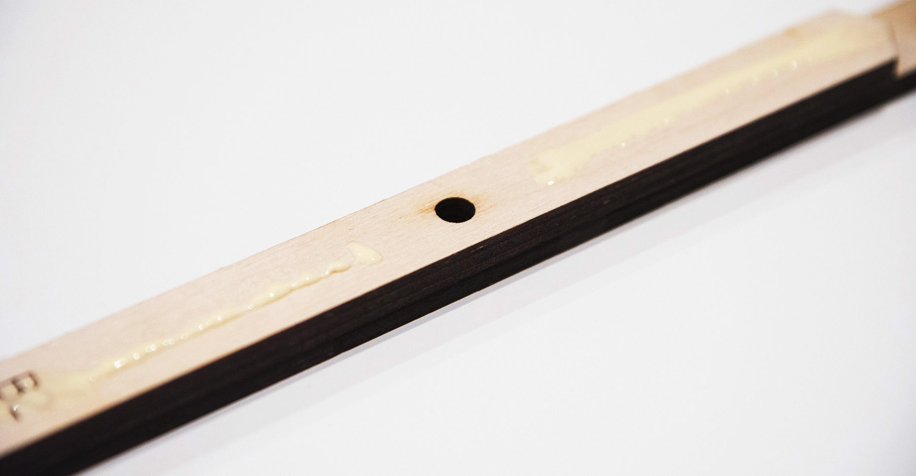
Fig. 7 - Keeping glue away from all holes except the dowel holes
Assemble all linkage sets in the same manner; use the long barrel bolts and the nylon bushings to align layers as you go. Bar A and bar F are identical.
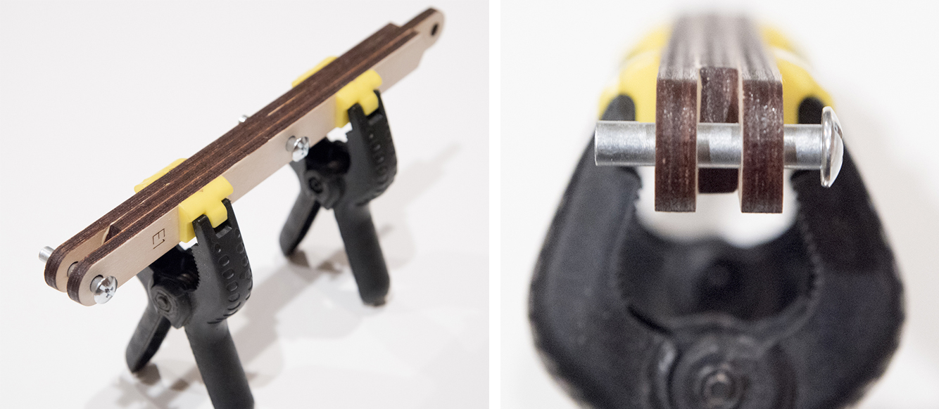
Fig. 8 - Using barrel bolts to carefully align layers
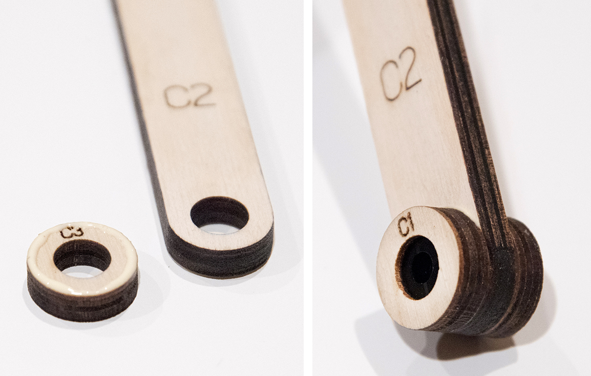
Fig. 9 - Use care when gluing bar C and D, you don’t need a lot of glue
For bar D use another piece of wood to space things properly while you clamp it. In these pictures I used pieces from the E bar, but shorter G pieces work great for this. Again, make sure the holes are aligned using the barrel bolts and nylon bushings.
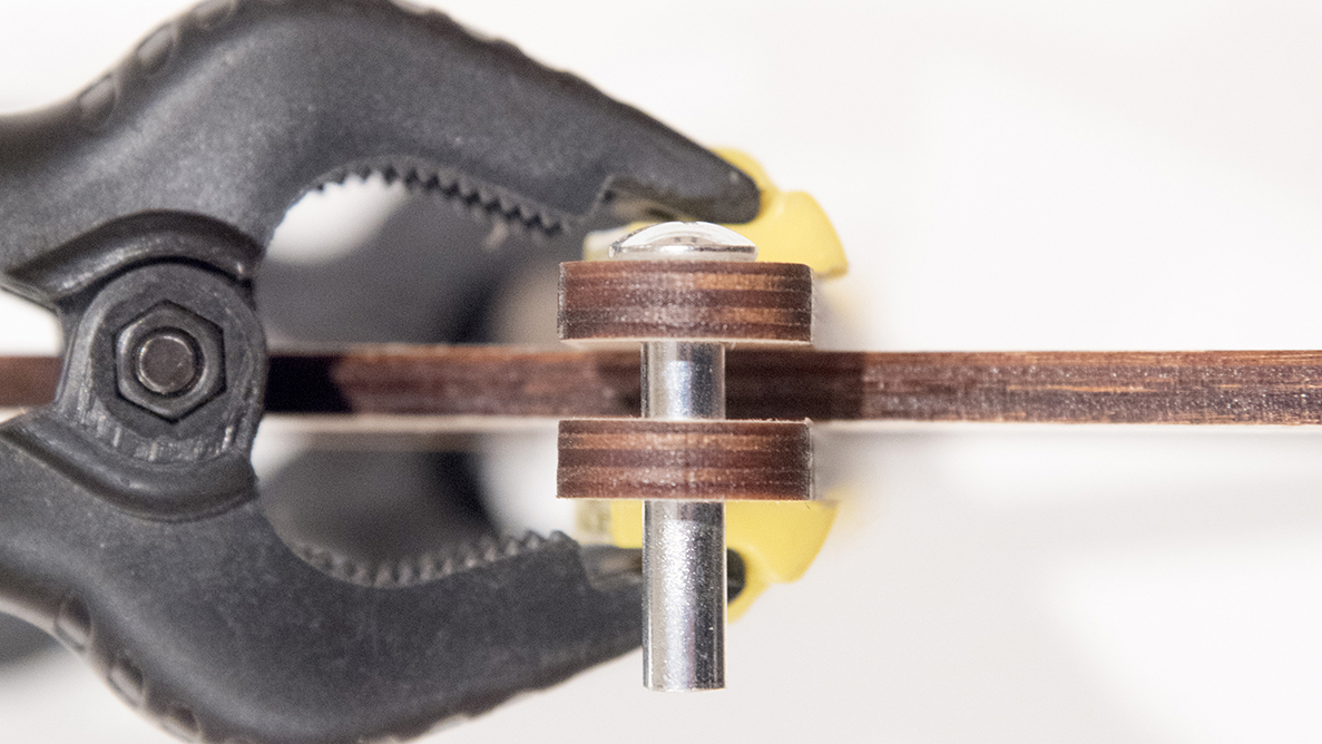
Fig. 10 - Check alignment from the ends as well
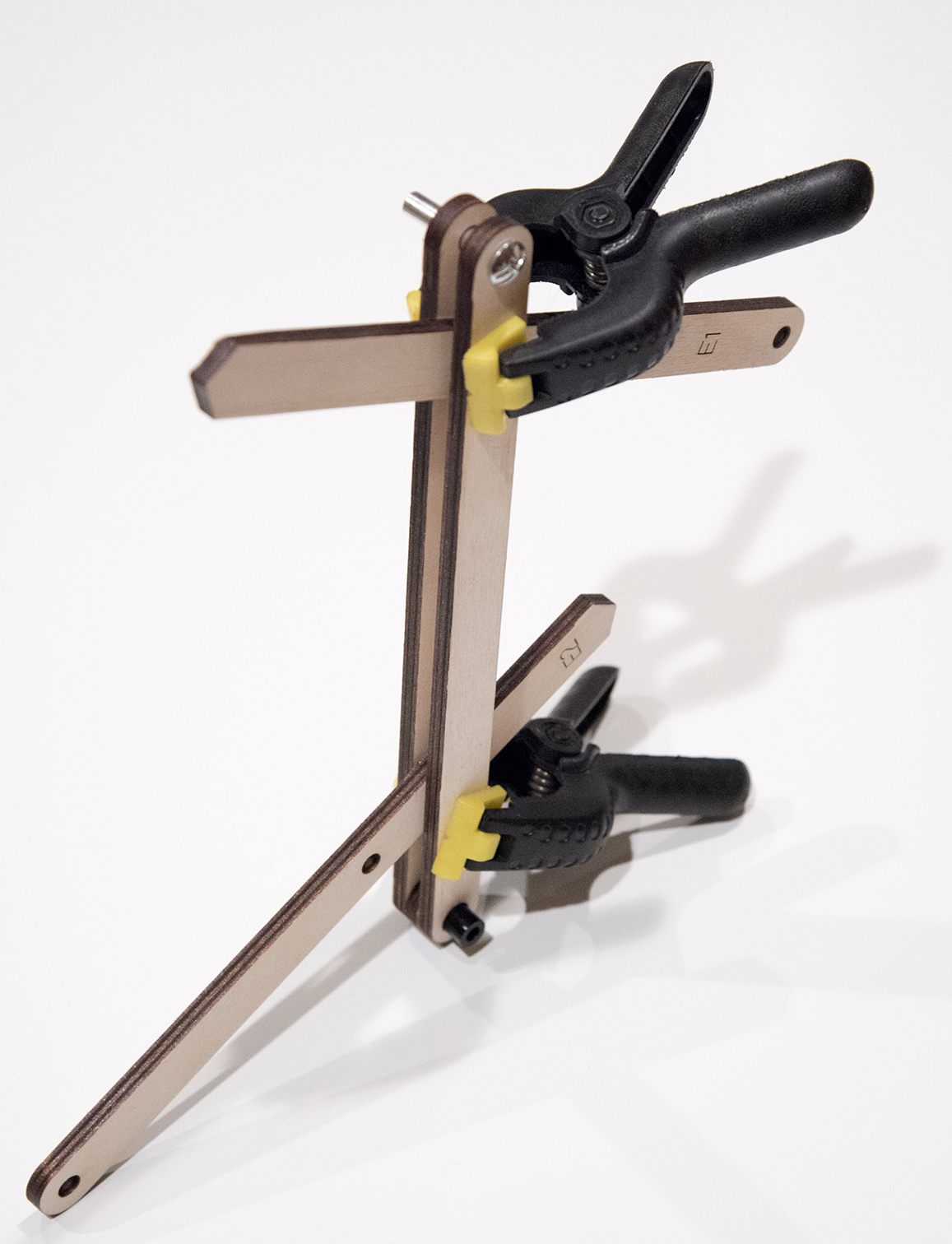
Fig. 11 - Bar D drying, using extra pieces as spacers
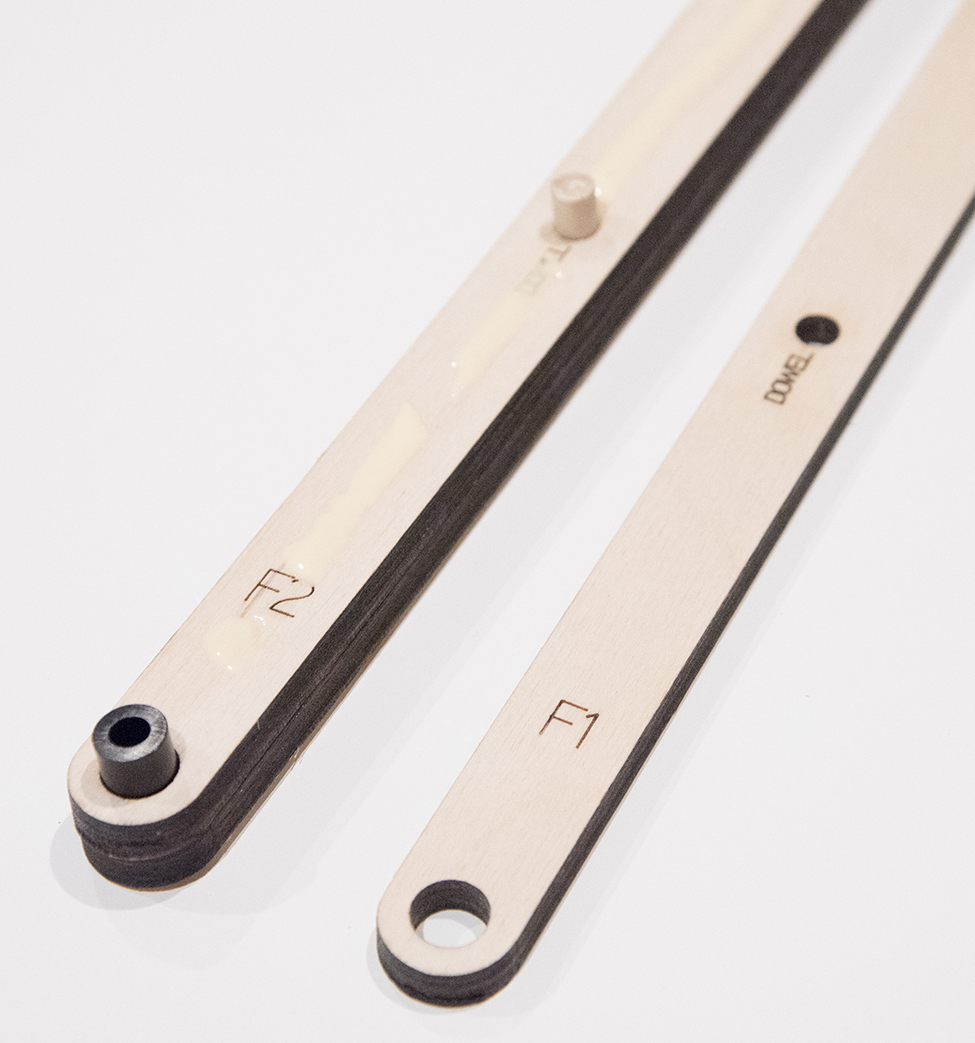
Fig. 12 - Bar F ready for final layer
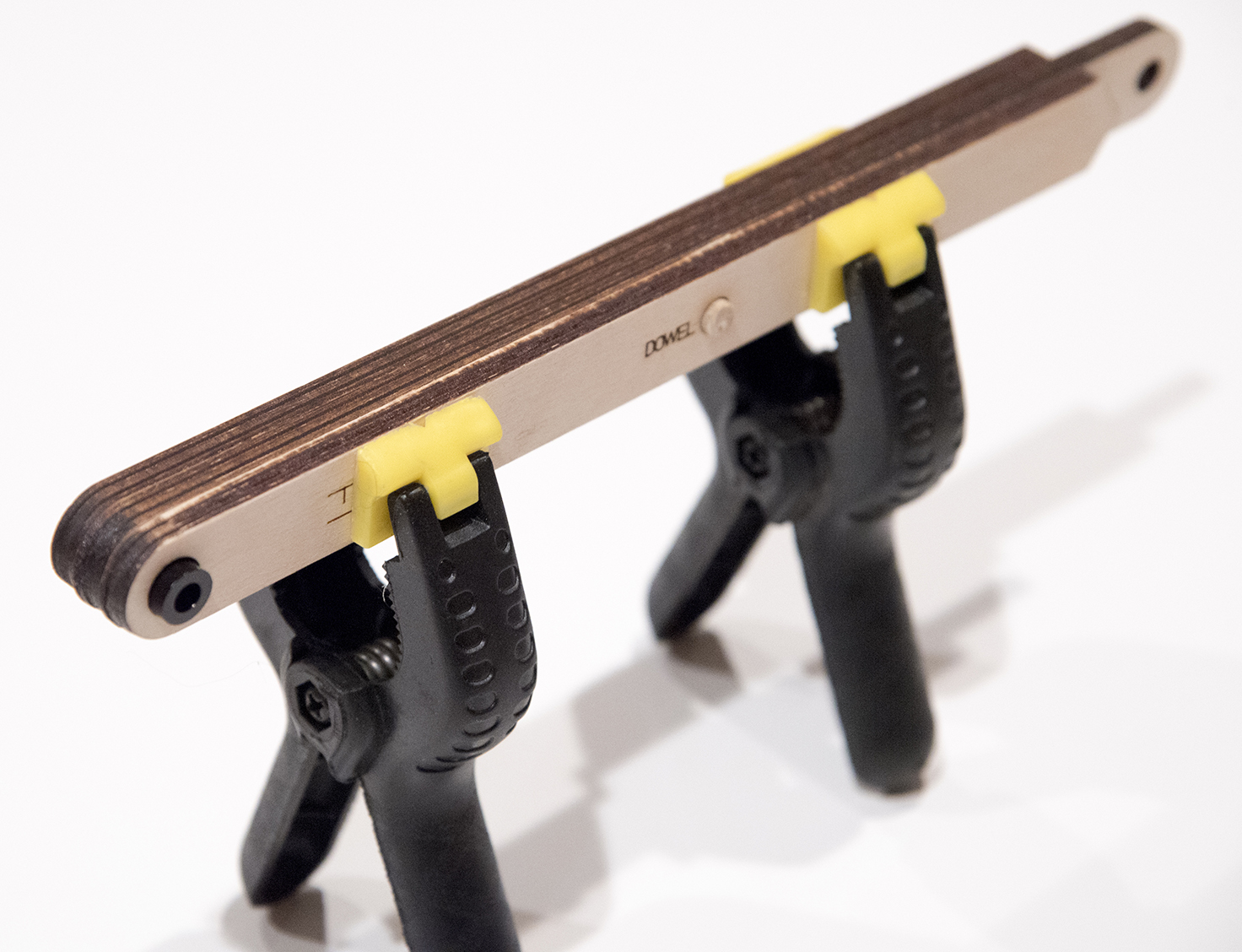
Fig. 13 - Bar F final glue-up (keep those bushings free!)
Now that all 6 bars are finished we will make the chain clevis connection using the G parts.
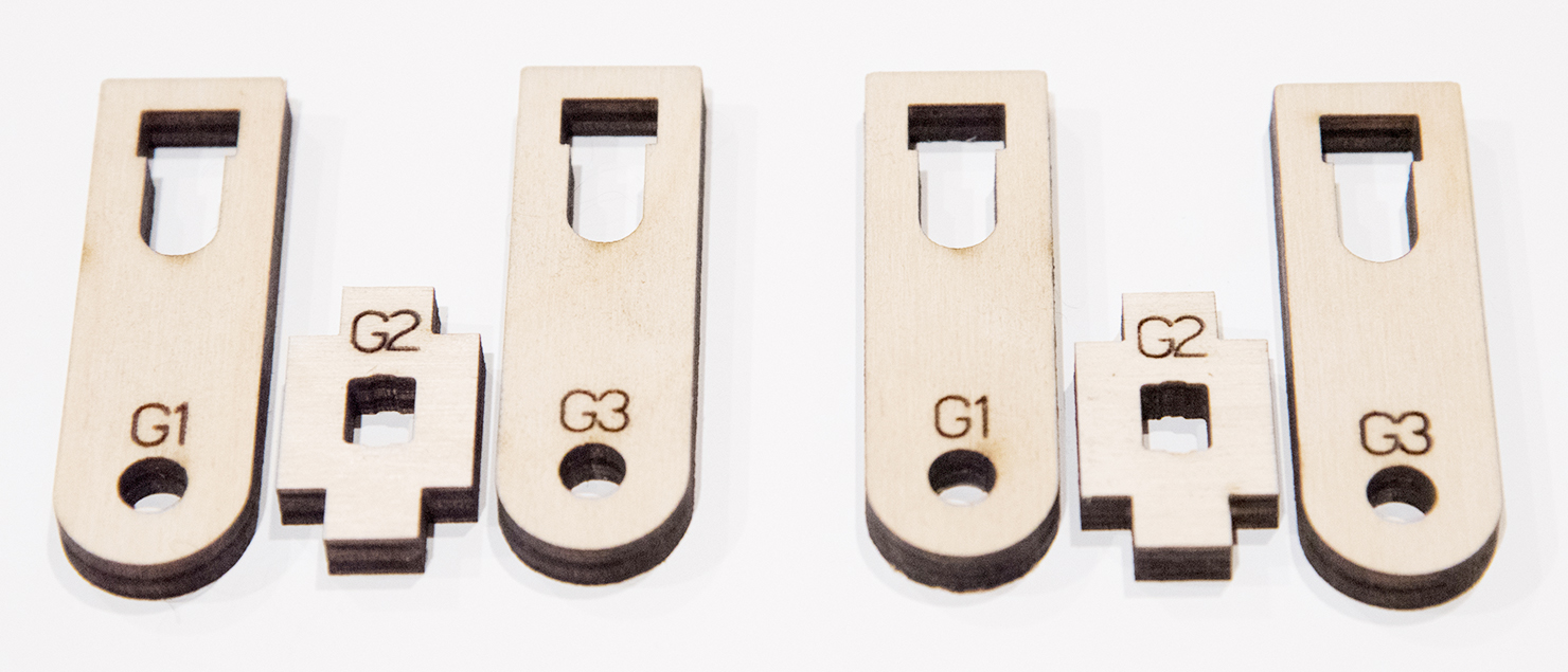
Fig. 14 - The clevis uses the same assembly style 1-2-3, but layer 2 fits into layers 1 and 3
Glue, assemble and clamp the three G parts using a barrel bolt to keep things lined up (fig. 15). The “U” shaped holes in G1 and G3 are to allow easy access to the chain attachment point if things ever need to be changed or adjusted.
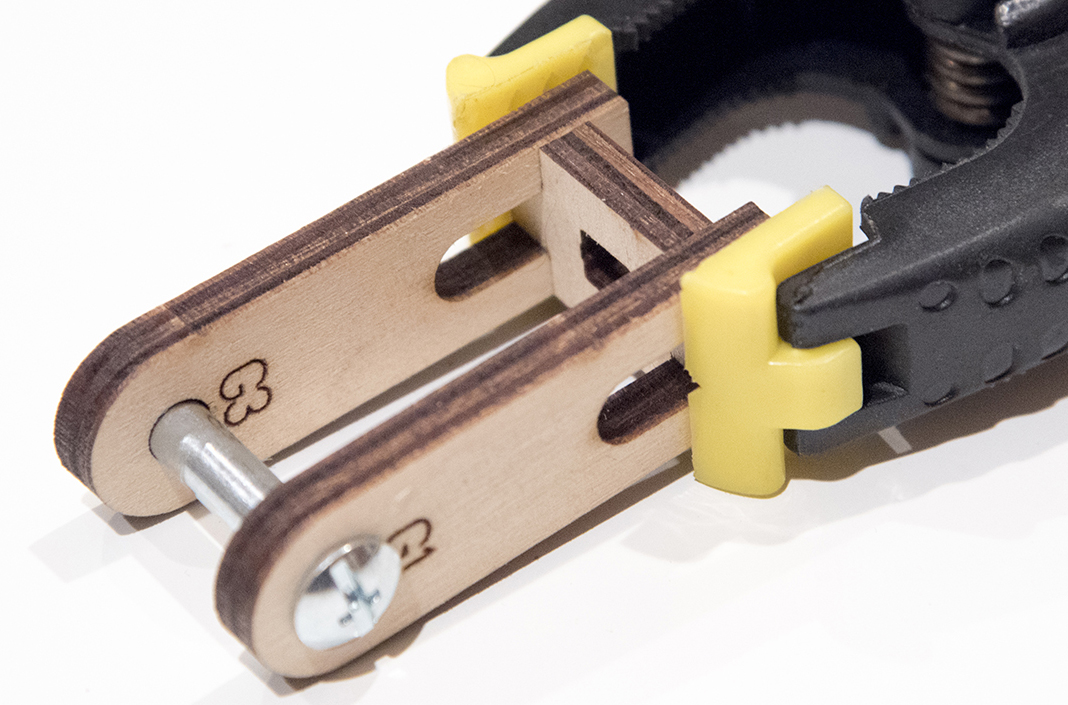
Fig. 15 - Gluing up a G clevis
To attach the chain to the clevis thread the chain through the rectangular hole and insert one of the included cotter pins into the the chain. Take care that the cotter pin rests perpendicular to the chain i.e. flat against the wood (fig. 17).
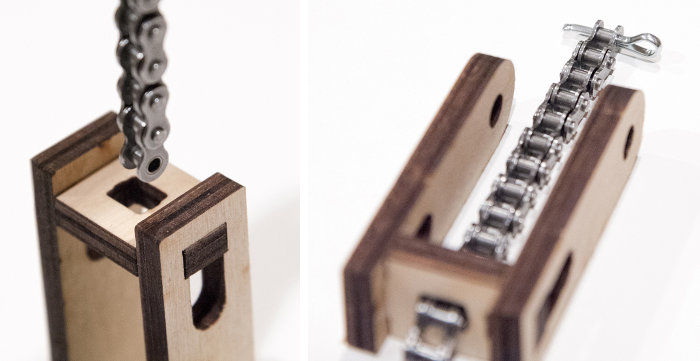
Fig. 16 - Insert chain into clevis, then insert cotter pin into chain
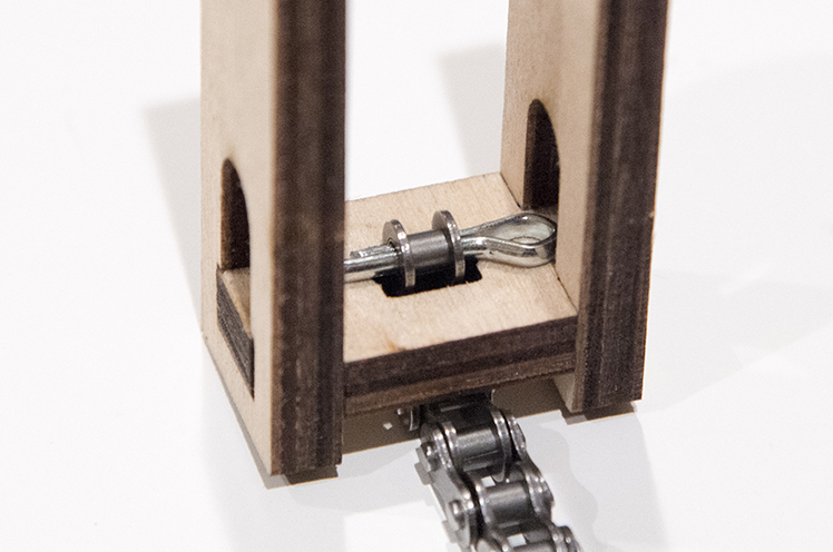
Fig. 17 - Cotter pin should lay flat against G2
To assemble the bars into a final linkage simply slip the joints together in the order shown in fig. 2 and insert a short female barrel bolt and a ¼” shoulder bolt. The barrel bolt can be tightened down snugly to keep it from coming apart. It will not pinch the joint.
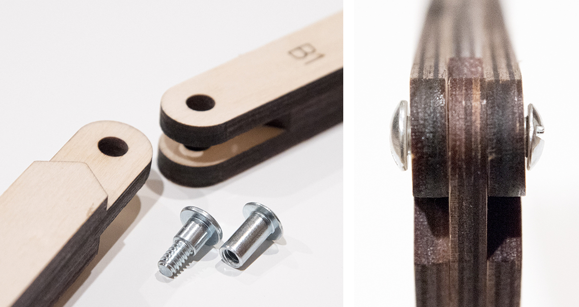
Fig. 18 - Short female barrel bolts are for the linkage joints, note the space between the heads of the bolt and the wood
Bar C and D must be assembled together so that C runs between the arms of D (fig. 19)
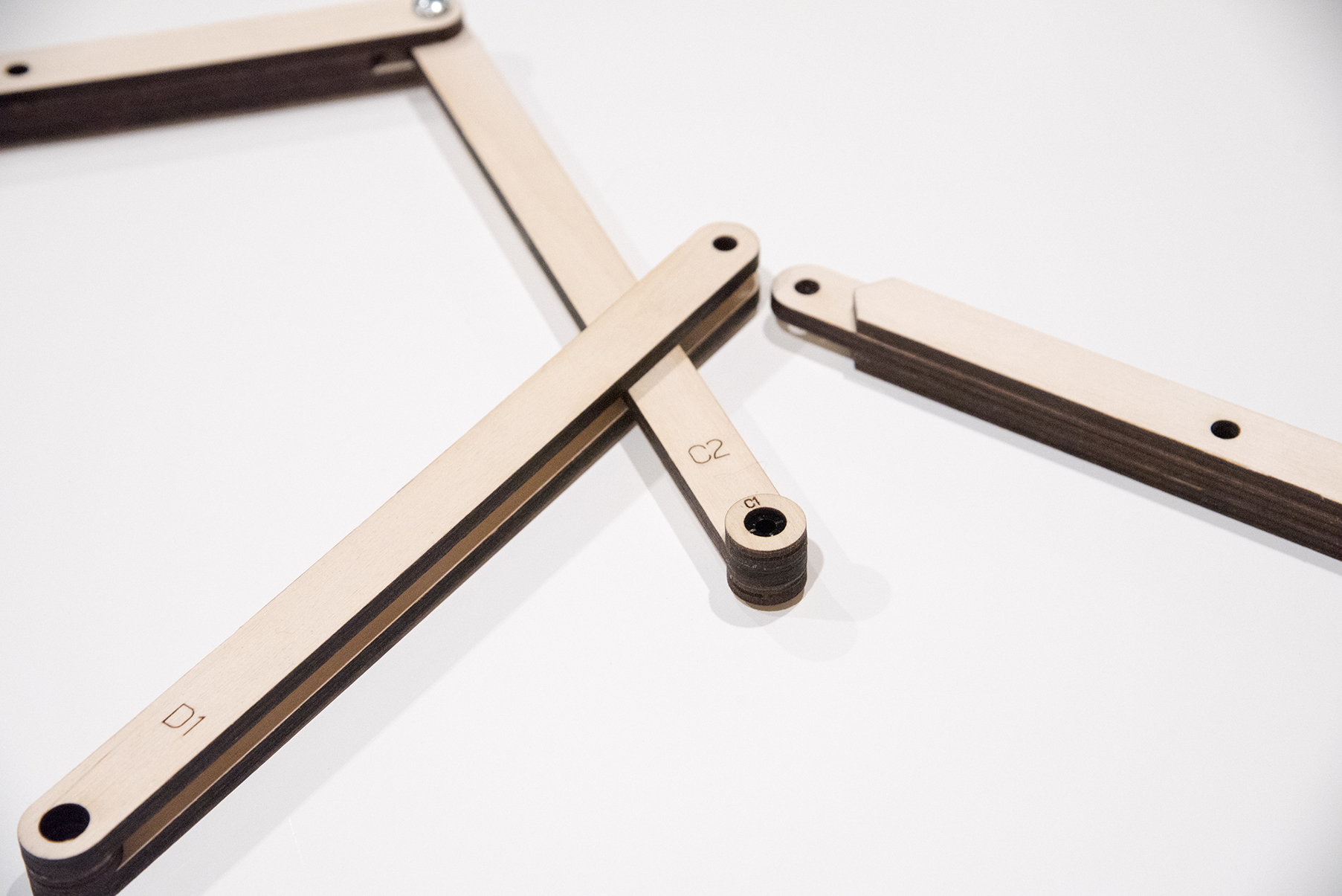
Fig. 19 - Bar D goes over bar C
The two clevises attach to bar B and bar E using the long barrel bolts and truss-head screws. These can be tightened down without binding the joint - there should be some space between the bolt heads and the wood.
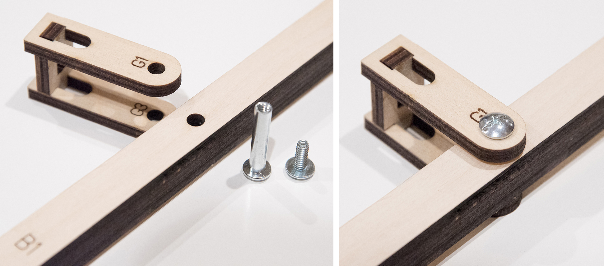
Fig. 20 - Clevis attachment using the long barrel bolts
The finished assembly should look something like fig. 21.
Fig. 21 - Finished assembly with all mounting hardware
To mount your linkage to your sled you need to determine how far off the sled it should be. If you were previously running a stock Maslow then you may have already determined a good spacing for your chains (the space between the work surface and the chain). A good rule of thumb is that the linkages should be mounted roughly near the sled’s center of gravity in the z-axis. This measurement is not extremely critical but if it is off by too much it could cause the linkages to bind or rub in a manner that is not conducive to accurate cuts. Ultimately the goal is to have the chains running parallel to the work surface, so the distance of your motors from the work should match your linkages. Once you have determined a good spacing (let’s use 2” as our example) then cut 4 blocks of wood 2” long. The blocks don’t need to be very big but they should have sufficient surface area for glue; I suggest about 1 ½” square. Drill a 3/16” hole all the way through each block in the 2” direction. Counter sink the 3/16” holes in the sled from the back to accommodate the head of the #10 machine screws. Insert the provided 4” #10-24 machine screws from the back of the sled and through the spacer blocks (See troubleshooting note about Z-Axis kit below). Add a washer (provided) to each #10 screw, then carefully attach the linkages with the nylon bushings sliding over the #10 screws. Add another washer to each screw then finish them off with a 10-24 nylock nut (provided). You should be able to tighten these down snugly and the linkages will still move freely. A small amount of friction is completely acceptable in this design. If things are binding then you need to find the friction points and fix it. Once you have tested your spacer blocks and are happy with the balance they should be glued securely to your sled. You can use it without gluing the blocks but things will be more structurally sound if they are glued.
Some of the linkage joints might require light reaming with a ¼” bit after they are glued, especially if some rogue glue seeped into a hole. The large holes can be reamed with a ⅜” drill bit if needed. I would suggest doing any reaming by hand (not with a drill) because it’s easy to take off too much material but it’s quite hard to put it back! That’s it!! You’ve built your very own Maslow Linkage! Give yourself a high five and go cut something awesome!
Troubleshooting
I don't know if people are experiencing these problems but these are the things I could think of that might go wrong. If you run into a different problem please let me know and I'll add it to the list!
The linkages seem to rub or bind.
- Sometimes there can be extra friction between bar C and D, carefully but liberally sand both sides of bar C in order to gain a little clearance. Also a smoother surface on these parts will help alleviate friction.
The linkages snag at extreme angles.
- Depending on how accurately (or inaccurately) your motors and linkage blocks are aligned you might experience a situation where a linkage bar "snags" on a mounting block when the sled is in a lower right or left corner of the workspace. It is best to have your linkages and motors on the same plane but this is not always possible; if your linkages are snagging you should chamfer or bevel the top edges of the mounting blocks.
I can't see my linkages; everything is black.
- Turn on the light. It's always smart to use your Maslow with the room lights on.
The wooden pieces don't look straight.
- There are a few kits in which you might notice the wooden pieces have a slight bow in them, this bow will go away when you glue and clamp the pieces together. Just ensure that you have it flat while it dries, I would suggest laying it on a table and putting weights on it. This is an extremely rare thing and has happened to less than 0.8% of the kits shipped. They were accidentally cut with the main wood grain running the wrong direction and I only found out after a few kits had shipped (less than 10 total). This should not affect strength or accuarcy to any detriment. If you have concerns or need a replacement piece please let me know.
The bars are not rubbing but there's still a lot of friction!
- Some friction in the joints is totally okay, things will loosen up with use. If you find there's too much friction in the joints you can gently ream them with a drill bit (by hand, not with a drill) or even use a smooth shank of the right diameter to "work" the mounting hole until it feels right. To understand why some friction on these joints is not a big problem you can read this post in the forums.
Z-Axis: I can't seem to cut all the way through the plywood when using the linkage kit.
- One user found that when they rotated their Z-axis kit out of the way of the lower right linkage block (rotated clockwise toward the exhaust port of the router) the top of their R22002 router would hit the lip of the Z-axis motor mount and get hung up. The user solved this by rotating the Z-axis mount such that the bolt for the linkage block could pass through the hole in the base of the mount and then installed the linkage block on top of it. Note, if you do this, you need to compensate for the extra height associated with the z-axis mount and screws.