The Meticulous Z-Axis
Files
Edit this page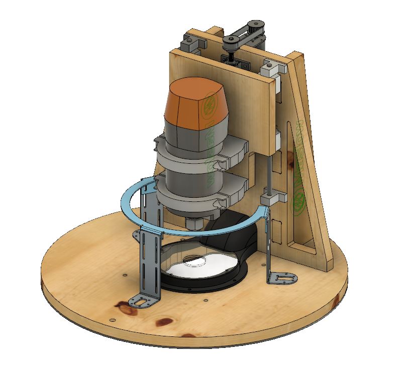 | Download FilesSource |
The Meticulous Z-Axis
An improved Z-Axis sled that uses the Rigid R2200 as the spindle
Instructions
Edit this pageMeticulous Z-Axis Updated Instructions
Tool list:
T1 = 1/4" single flute end mill
T2 = 1/8" single flute end mill
T3 = Engraving bit (I use a 30 degree one for crisp, thin lines)
T4 = 1/8" Stub drill, or center drill
T5 = 3/16" Stub drill
Programs:
There are two sets of programs in the NC files folder. One is for the standard version, the other is for the fully Maslowable version. Only run the one you need, or you will have spare parts. The program lists are as follows:
Standard Version:
MeticulousSled_18mmPly.nc - Cuts all the plywood components. Requires a piece at least 48" x 21" (1219.2 x 530mm) of 23/32" (18mm) high-quality plywood. Anything without voids in the plys will work. - Tools used: T1, T3, T4
MeticulousSledDustWindowAll.nc - Cuts the 1/8" clear plexiglass window for the dust chute. Requires a piece at least 6" x 6" (150 x 150mm) of 1/8" (3.175mm) clear plexiglass. Needs to be impact-resistant clear plastic. - Tools used: T1, T5
MeticulousSled_HDPE.nc - Cuts the HDPE/UHMW skid panel for the bottom of the sled. Required a piece at least 20" x 20" (508 x 508mm) of 1/8" (3.175mm) HDPE/UHMW. - Tool used: T1
In addition, the following parts need to be printed on a machine with a bed at least 200mm x 200mm (7 7/8" x 7 7/8").
1x Dust Hood Body V2.stl - This prints best with the hose port flat on the bed. Use supports touching the buildplate
1x Dust Hood Chute V2.stl
1x ZAxisLeadScrewNut_Bracket.stl
2x Spindle Bracket Top Back.stl
2x Spindle Bracket Top Front.stl
PLA is okay, but ABS or PETG is better. Any layer adhesion issues will severely compromise the strength of the components, so make sure to use an enclosure when printing in ABS. There have been reports of PLA degrading in warmer climates, if you live in a hot place it is recommended to use ABS or PETG.
The dust hood body is designed to use 3x 10-32 heat-set threaded inserts for the plexi window. After printing, use a soldering iron to set each of the inserts
The spindle bracket back is designed to use 4x 3/8"-16 heat-set threaded inserts. Two are on the back face, used to mount the clamp to the Z carriage. The other two are on the front face, and are used to bolt the bracket front on. Using a soldering iron, set each insert into the holes in the print.
Maslowable Version:
MeticulousSledFullyMaslowd18mm Plywood.nc - Cuts the majority of the plywood components. Requires a piece at least 48" x 21" (1219.2 x 530mm) of 23/32" (18mm) high-quality plywood. Anything without voids in the plys will work. - Tools used: T1, T2, T3, T4
MeticulousSledFullyMaslowd12.7mm Plywood.nc - Cuts plywood components for dust chute. Requires a piece at least 14 1/4" x 8 5/8" (360 x 220mm) of 1/2" (12.7mm) high-quality plywood. - Tools used: T1, T2
MeticulousSledFullyMaslowd3.175mm HDPE.nc - Cuts the HDPE/UHMW skid panel for the bottom of the sled. Required a piece at least 20" x 20" (508 x 508mm) of 1/8" (3.175mm) HDPE/UHMW. - Tool used: T1
MeticulousSledFullyMaslowd3.175mm Plexi.nc - Cuts the 1/8" clear plexiglass window for the dust chute. Requires a piece at least 6" x 6" (150 x 150mm) of 1/8" (3.175mm) clear plexiglass. Needs to be impact-resistant clear plastic. - Tools used: T1, T2
For the dust hood, you will also need a small piece of sheet metal. A piece of 0.060" aluminum will work great, as it can be cut with hand shears. For mounting the lead screw nut on the carriage, you will need a small piece of 1" x 1" angle iron. These can be bought at almost any hardware store. It will need to be cut 2" long, then drilled for the lead screw nut and mounting screws to the carriage plate.
Assembly:
For reference, the Fusion 360 model: http://a360.co/2jWip1u
After all parts have been cut, clean up and sand all components. Test fit all tab and slot connections before assembly. Drill out all the pilot holes for the wood screws using a 3/16" drill. There are 8x holes on the sled going into the z-axis spine, and 6x holes on the spine going into the gussets. Countersink each hole until a #8 construction screw sits below the plywood surface. A combined drill and countersink tool is ideal for the task. On the fully-Maslowable version, also drill the 4x holes on the dust hood body in the same fashion. Use a round-over cutter on the top edge of the sled to smooth it over. I think I used a 1/4 or 3/8" round-over bit. Feel free to round over any outside edges of the Z-axis spine.
Drill out all the mounting holes in the HDPE/UHMW pad with a 3/16" drill and countersink for a #8 screw. Make sure all the screw heads sit below the surface, or they will drag on your workpiece during cutting.
On the Z-axis carriage plate, drill the 16x bearing block holes out with a 7/32" (5.5mm) drill. Then, use a 13/32" (10.25mm) drill to drill out the 4x mounting holes for the spindle clamps. Using a drill press would be ideal to keep the holes perpendicular.
On the Z-axis spine, install the 12x 10-32 threaded inserts for the linear rails and lead screw. On the fully-Maslowable version, also install the 3x 10-32 threaded inserts for the plexi window. It also really helps to draw on the centerlines for the lead screw and linear rails. Use the threaded inserts as a reference, and take your time to get this right. If you miss the alignment in this step, your spindle may not be mounted parallel to the z-axis travel. Take your linear rails and lead screw to check that they are already cut to the correct length. Both should be 250mm long.
A couple of coats of tung oil is recommended to protect the wood, but it is not necessary.
Begin by assembling the Z-axis frame. Glue the gussets to the spine, then attach with #8 x 1 1/2" wood screws.
To assemble the 3D printed dust chute, place the chute on the sled roughly in the spot where it will be attached. Take the Z-axis frame and fit the chute into the slot for it, then align the frame tabs with the slots in the sled. Place the dust hood on the sled, aligning it with the cutout in the center of the sled. Align the chute with it, then secure both parts using #8 x 5/8" wood screws.
To assemble the Maslow-able dust chute, glue each of the 1/2" plywood parts down to the sled. Slide the aluminum sheet metal into the slot in the top, making sure that it is fully seated in the slots. It doesn't hurt to put a little caulking around the edges. Hold the plywood parts together using clamps and rubber bands. Screw the dust hood down, aligning it with the dust chute and the cut-out in the sled. Make sure to test fit the Z-axis frame over the chute before the glue dries to make sure all the parts will fit.
If you want to glue the frame down, remove it now and glue the mating faces. If you glue the frame down, keep in mind you will not be able to change out the dust chute in the future. If it gets damaged or the PLA degrades, you won't be able to replace it without building another Z-axis. I glued mine, and it is stronger that way, but it fully captures the dust chute.
Carefully turn over the sled so that you have access to the bottom holes for attaching the Z-axis frame. Use 8x 1 1/2" wood screws to secure the frame to the sled.
Next, assemble the Z-axis carriage. Slide the bearing blocks onto each linear rail, then insert 16x M4 x 0.7 x 30mm screws, taking care not to tighten them all down until the end. Use a square to align the bearing blocks to the spindle centerline. Take care to get this right, if you miss the alignment in this step, your spindle may not be mounted parallel to the z-axis travel. Attach both spindle clamp backs to the carriage plate, using 4x 3/8"-16 x 1" flat head screws, again taking care to not fully torque them. Flip over the carriage and place the router in the spindle clamp backs. Make sure the router is fully aligned with the clamps. Bolt the clamp tops on, making sure to keep the clamps centered. It helps to move back and forth between the two bolts until they are evenly clamped. Once the spindle clamps are fully torqued, flip the carriage back over again and fully torque the flat head screws holding the clamps to the plate. To make the carriage assembly lighter and easier to handle, unbolt the router from the spindle clamps, taking care to not shift the spindle clamp backs.
Now, assemble the lead screw components. Start by sliding one pillow block on, leaving it approximately 1" (25.4mm) from the end. Next, set the pulley at the top of the lead screw. Note, there are two different sized pulleys in the kit. Because the output shaft of the motor and lead screw are different diameters, it is impossible to mix them up. Then, attach the lead screw nut to the printed (or angle iron) bracket. Thread the nut onto the open end of the lead screw, and run it up until it's close to the pulley and pillow block. Slide the bottom pillow block on, then line up the pillow blocks with the center set of 10-32 threaded inserts on the spine. It helps to do this step with the frame laying flat. Insert the 4x 10-32 x 3/4" screws, taking care not to tighten them down. Align the lead screw with the centerline on the spine. Take care to get this right, if you miss the alignment in this step, you spindle may not be mounted parallel to the z-axis travel. Once the lead screw is aligned, torque down the mounting bolts.
To install the carriage on the spine, slide the rail mount blocks onto each end of the linear rails. Place the carriage assembly on the face of the spine and line up the linear rail mounting holes with the remaining 8x 10-32 threaded inserts. Thread in the 8x 10-32 x 3/4" screws, taking care not to tighten them down. Align the linear rails with the centerlines drawn on the spine. Snug up the top screws and torque down the bottom ones. Align the lead screw nut backet with the top edge of the carriage plate. Using a pencil, make alignment marks for the bracket on the top edge of the plate. Remove the top linear rail mounts. Slide the carriage assembly out of the bottom mounts and flip it over. Transfer your lead screw nut alignment marks down the back face of the carriage plate. Slide the linear rail out of the bottom pillow block by enough to thread the nut and bracket off. Once the bracket is off, slide the lead screw out of the top pillow block and set aside.
Take the lead screw nut bracket and line it up on the carriage plate. Set it approximately 1/4" (6.35mm) from the top edge. Screw it in using #8 x 5/8" wood screws, making sure that the lead screw nut is properly aligned. Take care to get this right, if you miss the alignment in this step, your carriage may bind.
Slide the carriage assembly back onto the bottom rail mounting brackets. Slide the top mounting brackets back in place, and secure them to the spine. Once again, check the rail alignment before fully torquing the brackets down. Take care to get this right, if you miss the alignment in this step, your carriage may bind.
Slide the lead screw back in through the top. Thread it into the nut, and continue to thread the screw until it is through the bottom pillow block and the pulley is sitting just above the top the spine. Ideally, the top of the pulley should be 1" from the top of the pillow block below it. Secure the set screw in the top pillow block, then move the carriage up until you can access the bottom pillow block and secure its set screw. By hand, move the carriage plate a dozen times through it's full travel. Feel for any place where there feels like there is resistance. If you find any uneven resistance in it's travel, check you alignments and correct as needed until the travel feels smooth and consistent. Once you're done, lower the axis until the bearing blocks are resting on the bottom mounting brackets.
Screw down the dust window in the dust chute body with 3x 10-32 x 1/2" screws with the notch facing towards the right if you're facing the spine. Take your router and carefully place it in the spindle clamps. Make note of the spindle lock button on the side and line that up with the corresponding notch in the window. If the notch looks like it's backwards, that's just cause you put the window on the wrong way. Don't worry, I did it too. Just flip the window over and it will line right up. Let the router collet rest on the workbench below the sled, and secure the spindle clamps to the router. Again, take care to tighten down each side evenly so the clamp is centered. Flip up the sled so that the bottom is exposed again and attach the HDPE/UHMW anti-friction pad to the bottom face using #8 x 5/8" wood screws. With the pad on the bottom of the sled, the face of the collet on the router cannot get within 1/8" of the workpiece, and will prevent crashes. If the router height isn't set right, the machine can drive the collet into the workpiece. With it spinning 10-25k rpm, that will cause a fire in a hurry.
I had to mount my Z-axis motor in it's bracket with the output shaft closer to the spine to get my belt tension right. Depending on the pulleys and belts you purchased, you may need to mount it one way or another. Install the timing belt pulley on the z-axis motor. Tilt the frame up so that the spine is vertical. Hold the motor in place, and then place the timing belt over it. Set your belt tension, then screw the motor down using #8 x 5/8" wood screws.
Mount your linkage/ring system to your sled. Instructions vary depending on the setup, but this system accomodates the ring system, the 45 degree linkage system, and the top mount linkage system. If you are using the Fusion 360 file to program your specific setup, you can output only the required mounting holes for your setup. A common adjustment needed for all systems is that the chains need to be 4 1/2" (~120mm) above the spoilboard. This is due to the higher center of gravity of the entire assembly. The ring system should be able to adjust that far, but the linkages will need spacers to get them to the right height. I have 3D printed ones for my own setup, which uses the 45 degree linkage system. The risers need to be stable enough to not deflect while the machine is in use.
Install your weights to the sled. I use some steel bars that weigh about 3 1/2 lbs (1.5 kg). I measured my whole assembly without weights and it came in at 23 lbs (10.4 kg). Your total sled weight should be around 26-28 lbs (12-13 kg) ideally.
From here, install the sled on the machine. Attach your chains to your linkage/ring. Attach the dust collection hose. For both dust hoods, I used a 2 1/2" hose as my standard. Adaptors can be bought or printed for other hose sizes. I like to have a "parking position" for my sled, which is simply a piece of 1/4"-20 threaded rod bolted above my cutting area off to the right. I used to center mine, but with the dust collector hose handing off the bottom its easier to have it offset to one side so you can load and unload the machine easier. You will have to drill a clearance hole in the top of the sled for the threaded rod.
Installation:
This is the easy part. With your sled on your machine, hook up the router power and the motor cable. It may be wise to upgrade the z-axis motor cable with a shielded cover. Otherwise, you will need to route the power and motor cables separately to avoid having signal interference.
The only settings change we need to make is to change the Z axis pitch. The value you enter in here is going to depending on the gearing you have at the motor. I feel pretty good about a 3:1 ratio, the axis moves as quickly as I need it to and it doesn't struggle with it. The lead screw has a pitch of 8mm/rev, so you simply multiply that pitch by your gear ratio. Open up Ground Control/Web Control and go to "Maslow Settings". Find the setting "Z-axis pitch" and enter in the following depending on your gearing:
3:1 = -24 (ex: 30T and 10T, 60T and 20T)
2:1 = -16 (ex: 20T and 10T, 40T and 20T)
1:1 = -8 (ex: 10T and 10T, 20T and 20T)
Make sure you enter a negative value! If you set a positive value, the axis will move backwards. Because the motor is flipped 180 from the stock position, we need to tell Ground Control to flip the rotation direction.
Check to make sure that your pitch is set correctly. If you have one, set up a dial indicator on your sled so you can measure the amount of travel on the axis. If you don't, you can place a ruler next to the linear rails, line up so that you can see how much the axis moves with each command. You may need to tape it down to keep it from moving. Open up the Z axis menu and raise the Z axis by 1mm (0.040"). The point of moving it a small amount is twofold. First, if you put a positive value in for the pitch, you will only crash a little bit and it won't break anything. The second is to verify that your pitch isn't significantly off. Once you have verified the direction is correct, check the distance that the axis has moved. Command it up and then down the axis in small increments that you can easily read with you indicator or ruler. Some backlash is normal, I saw about 0.1mm (0.004") in my setup. If you want to, you can eliminate some of that with anti-backlash lead screw nut. Once you have verified your axis is moving the correct distance, jog it by 10mm (3/8") increments and make sure it still is moving the correct distance.
If you are having no issues with the pitch, congrats, you're all set! Go make some cool stuff! Include a lot of Z travels in your programs for funsies.
If it's not going the right distance, don't worry. Check your math first. If you can't find the problem, you can use the error you're seeing to derive what pitch you should have.
To calculate the movement error:
E = D2 / D1
Where:
E = Error
D2 = Distance the carriage actually moved D
1 = Distance the carriage was requested to move
To calculate the corrected setting:
C = Z * E
Where:
C = Corrected Z-Axis mm/rev
Z = Z-Axis mm/rev from the test
E = Error
Forums
Z-Axis - $67.92 before shipping
300mm Linear rail and lead screw kit - Amazon - $35.99
XL 10 tooth Timing Pulley for lead screw - Amazon - $6.69
XL 30 tooth Timing Pulley for servo motor - Amazon $9.75
XL 1/4" x 9" timing belt - Amazon - $11.99
12x 10-32 Threaded inserts for softwood - Amazon - $3.50
An assortment of #8 wood screws
2x 1/4-20 x 1 1/2" hex cap screws, with nylock nut and washers
12x 10-32 x 3/4" Pan Head Machine Screws
16x M4 x 0.7 x 30mm Pan Head Machine Screws - linked pack is 2x per pack, order 8x for needed quantity.
Spindle Clamps:
Dust Hood:
3x 10-32 Heat-set Insert - Amazon - $8.49
3x 10-32 x 5/16" Flat head Machine screws
Some form of plastic glue or epoxy to help glue the chute and body of the hood together.