Big Z-value display
Files
Edit this page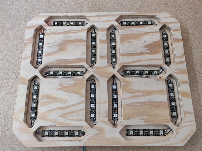 | Download FilesSource |
Big Z-value display
Be able to see the current Z value of your maslow from all over the workshop
Instructions
Edit this pageBuilding instructions
Materials
- 1x arduino (any will do - I'm using a Pro Mini)
- 1x 5V power supply for the display. you CAN NOT use the maslow power - you will get USB errors and lose your work.
- 57x WS2812/NeoPixel cut in separate strips with 4 in each segment. leave a single for decimal separator
- ??x connection wire (the led strips need 3 connections between each segment)
- 1x Front plate cut from SVG or DVG file
- 1x Back plate cut from SVG or DVG file
- optional: opaque acrylic cut from the same pattern as the Back file.
Program the arduino
Just like the maslow firmware we need to program the arduino. In the repository there is a .ino file which you will have to program to the arduino board of your choice. In the first few lines of code there are a few definitions of how many pixels per segment (default is 4) and which pin you want to connect to. I chose pin 6 because - default. you can change it to whatever you want. Remember: If you change the number of pixels per segment you will have to update the offset values in the code.
Assemble the display
Place the front piece on top of the back piece. Using a pencil lineout the cutouts for each segment.
on the back-side of the front piece you will have to carve a channel for the wiring. it's not important where the channel is but from experience it's easiest if you try to hit the middle of the segments where possible Remember: If you change the segment orientation which is quite likely if you don't route the segments like I have - you will need to update the segment-offset values in the code. othervise the segment decoder will not work properly.
Mark the channels on the base-board.

- Using the glue on the back-side of the LED strip put down the segments

- solder time! connect all the segments with Ground, Power and Signal wires. the last pixel is the decimal indicator. Using the markings the wires can be laid out more easily. This is an old picture of the display - you should have a decimal point as the last part of the string

Wiring to the Maslow controller
This is perhaps the most tricky bit. I did have some trouble with my configuration being blown to bits so please power down your system when doing this
you will need to connect two wires from the Maslow controller: Ground and 'TX' - yes, you have to connect to the transmit pin since we're listening in on the communication FROM the controller (not the data sent TO the controller)
- Ground connects to ground on the display controller
- TX from the Maslow connects to RX on the display controller.
That's it - you should now have a huge display for your machine!