## Issues addressed:
Files
Edit this page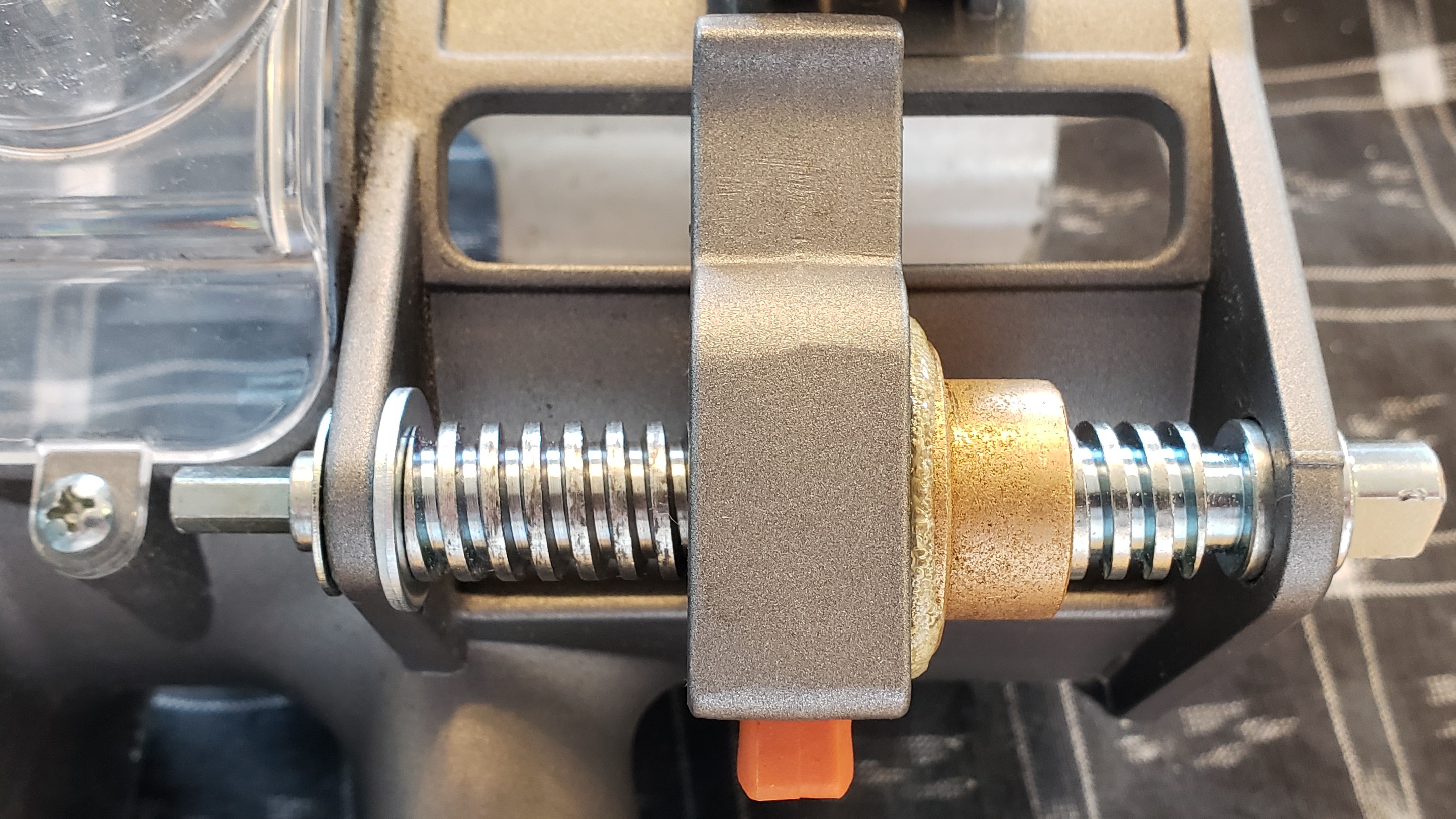 | Download FilesSource |
Inexpensive fixes for z-axis slack imprecision on Maslow CNC
Issues addressed:
- Eliminate play in z-axis worm
- Reduce imprecision due to tilt in the connection clip between worm and router body
Issues in research:
- Multiple drag points in z-axis and router assembly
- Modified z-axis clip can cause enough drag to rotate z-axis clip, disengaging it
Routers these fixes can be applied to:
| Router Model | Ridgid R22002 |
|---|---|
| Loose Worm | Y |
| Angled Mech. Fuse | Y |
| Weak Fuse Spring | tbd |
| Friction Points | tbd |
Instructions
Edit this pageTHE SITUATION
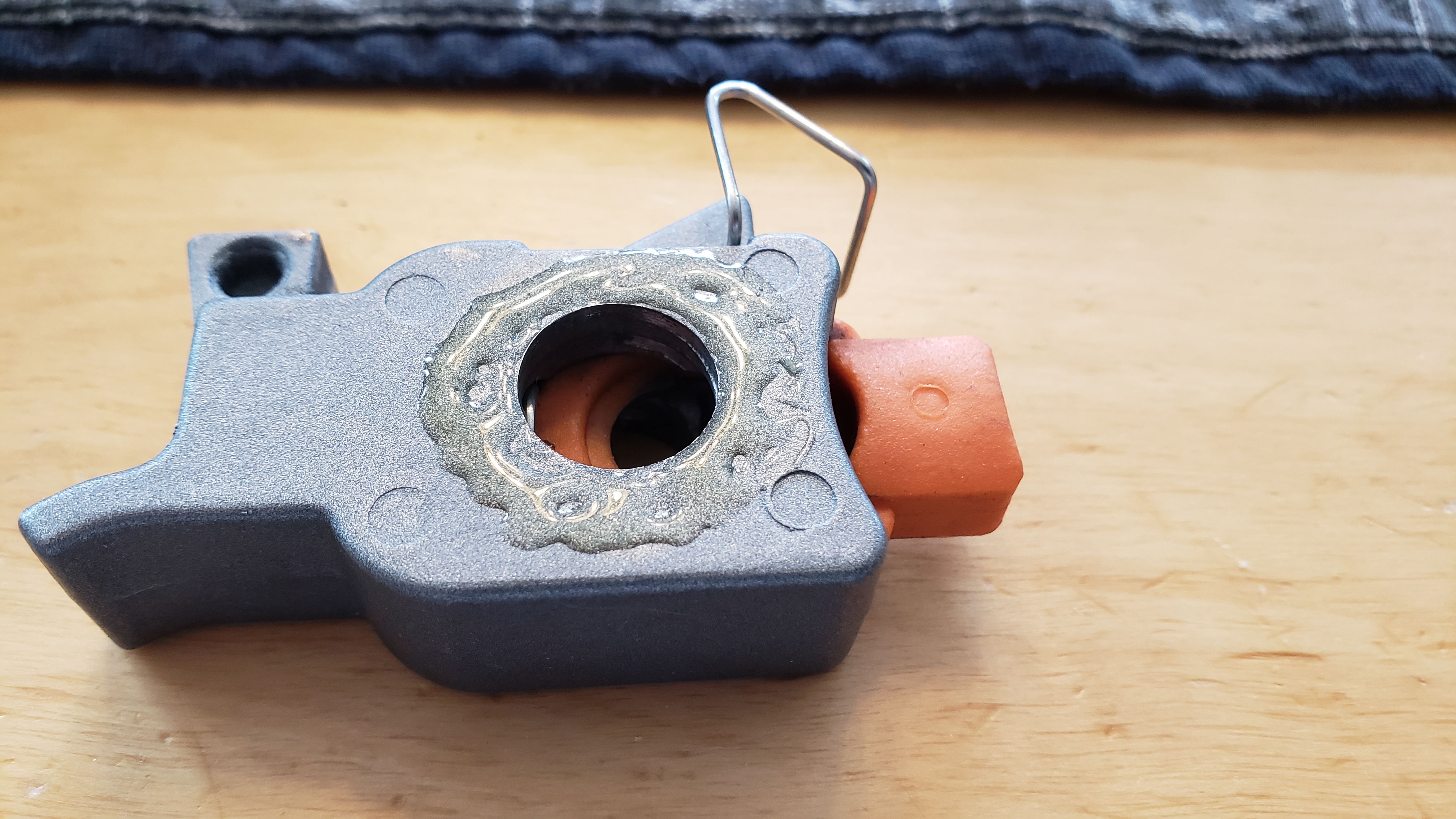
The router motor is inside of a metal sleeve, and the sleeve has a wide slot cut out of the side. There is a rectangular cutout in the router motor body that travels up and down, visible in this cutout. A spring-loaded clip pushes a rectangular-shaped tab into the rectangular-shaped cutout in the motor body. This clip is what the z-axis adjustment screw (technically a 'worm') pushes up and down when the screw rotates.
THE PROBLEM
These are not precision-machined parts, and either the cutout in the motor body is too big, the tab on the clip is too small, the hole in the clip has problems, the worm can slide up and down parallel to the router body - or a combination of all four.
TESTING
With my Ridgid R22002, the problem was the hole in the clip used by the worm. In testing, here's what happens when we zero the bit and drill two 10mm holes: (numbers rounded for illustration)
ZEROING ERROR
- The bit is 10mm above the surface, The clip is perfectly perpendicular to the router body (level).
- The z-axis is told to move 5mm down. The worm side of the clip moves 5mm down while the router body doesn't move.
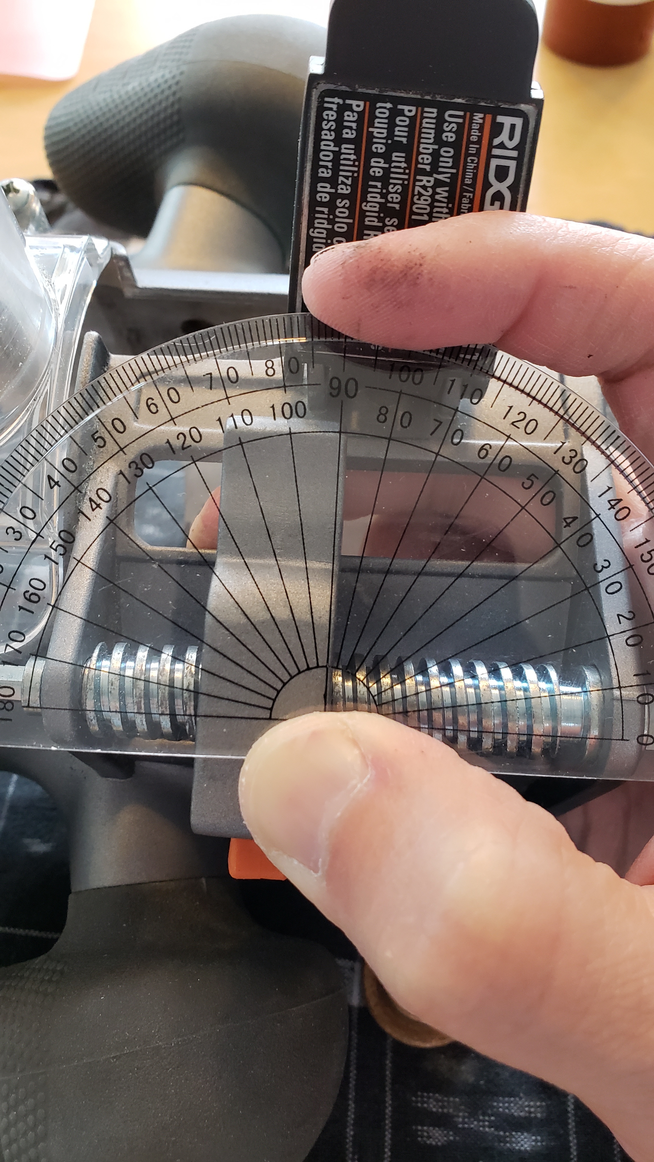
- The clip is now tilted "down", with the worm side 5mm lower than the router side.
- The z-axis is told to move 10mm down. The bit is now zeroed, just grazing the surface. The clip is still angled 5mm down, lower on the worm side.
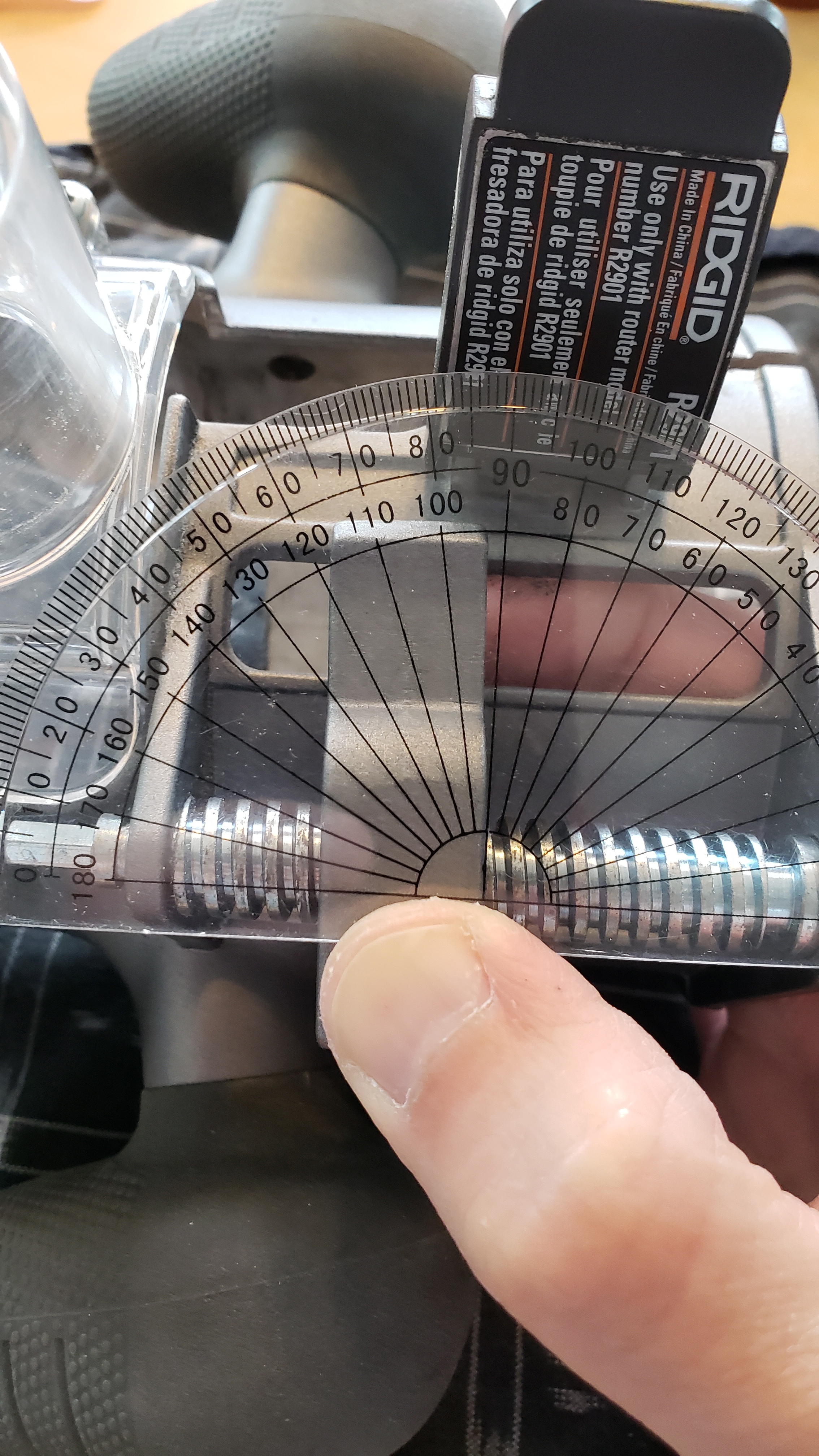
- The z-axis is told to rise to its traverse height of 5mm. The worm side of the clip is raised 5mm, and the clip is now level. The bit is still zeroed on the surface of the wood.
OUTING ERRORS
- The z-axis is now told to drill a 10mm hole. The worm drive turns enough to move the worm side of the clip down 10mm.
- The first 5mm of downward travel is used to angle the clip down on the worm side, with no change in the depth of the bit. The remaining 5mm push the bit 5mm below the surface.
- The worm now retracts 15mm, 10mm to clear the surface and 5mm to get to the safe traverse height.
- The first 5mm is used to make the clip level, perpendicular to the router body. The bit depth has not changed and is still 5mm below the surface.
- The next 5mm is used to angle the clip up, now with the worm side 5mm higher than the router side. The bit depth has not changed and is still 5mm below the surface.
- The final 5mm pulls the bit up 5mm. The bit should be 5mm above the surface but is zeroed on the surface.
- This process will repeat in the second hole.
This is the best-case scenario. Here's where it gets worse:
Shortly afterward, you'll notice the holes are 5mm too shallow. Adjusting the zero point 5mm down will be a mistake - the bit will drill 10mm-deep holes, but carve a 5mm deep path through the material in-between holes when it should be 5mm above the surface.
Moving the bit up until the bit is flush with the surface will leave the worm-side of the clip 5mm higher than the router side. Zeroing here will mean a 10mm travel of the worm before the bit moves. Going from a 5mm traverse height to create a 10mm hole will then be 15mm of worm travel:
- The first 10mm will move the worm-side of the clip from "up" to "down", with the bit still 5mm above the surface.
- The final 5mm of worm travel will zero the bit on the surface, when it should be 10mm below it.
- Telling the z-axis to rise to traverse height will then put the bit perfectly 5mm above the surface and leave no hole at all.
This is the part where you start going crazy.
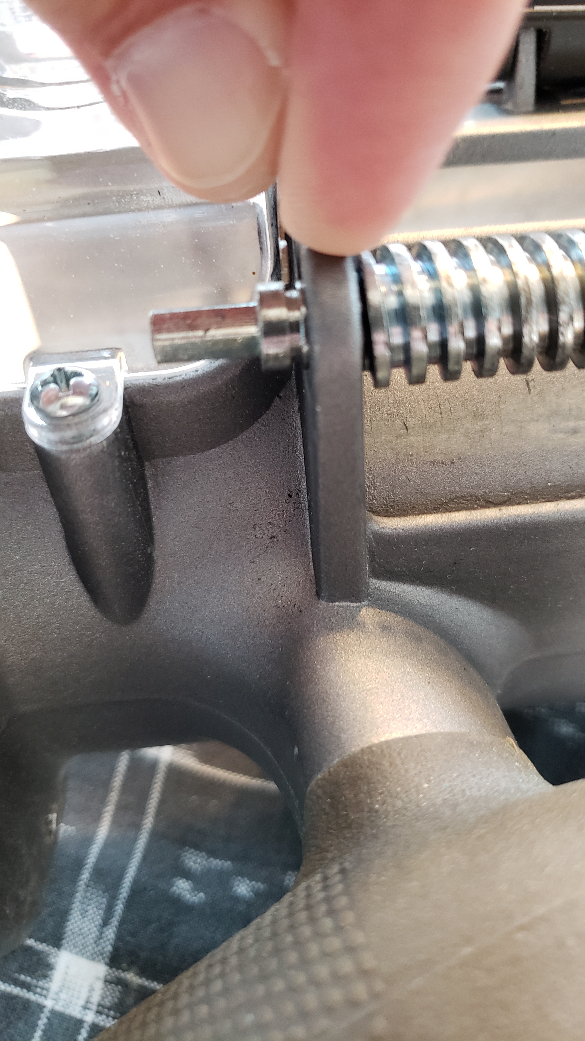
Both of these pictures are with the clip in the same place, and with finger pressure on the router tab either way"
arnoldcp Did a great write-up on how to bore out either side of the clip, leaving a small lip inside, and gluing speacers into the bored-out hole to make it wider.
Here's my problem: I don't have the facilities to precisely machine out the hole in the clip exactly at a 90-degree angle and to a certain depth so the spacers have a supportive lip to support them.
A few trips to Lowe's later, and here's what worked for me:
PLAY IN THE WORM HOUSING
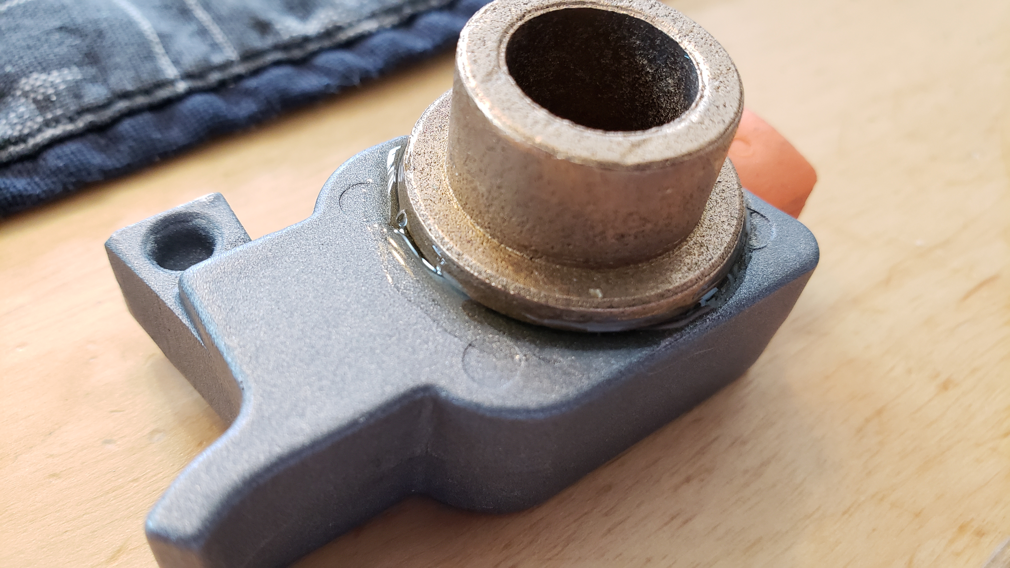
The worm is not secure in its mounting. It can move parallel to the router body by a few mm, and you can "rattle" it by hand, up and down.When pressed all the way down, there is ~2.5mm gap between the lower hole surface and the far side of the cutout for the c-clip. Since the c-clip is about 1mm thick, this leaves 1.5mm of play in the worm. This movement needs to be eliminated so the worm cannot slide in parallel with the router body, otherwise the z-axis will be moving the worm up and down for the first ~1.5mm instead of the router bit.
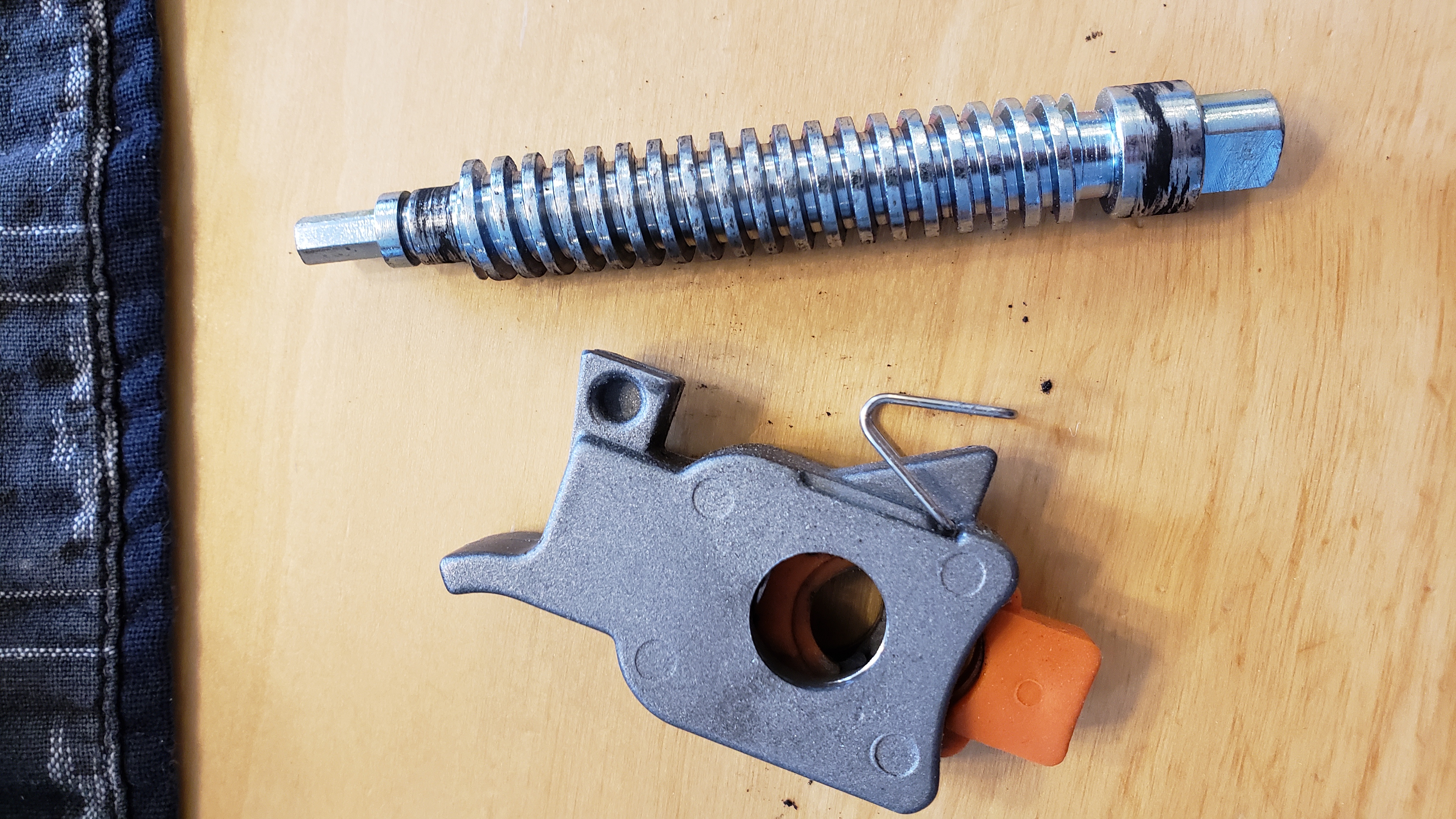
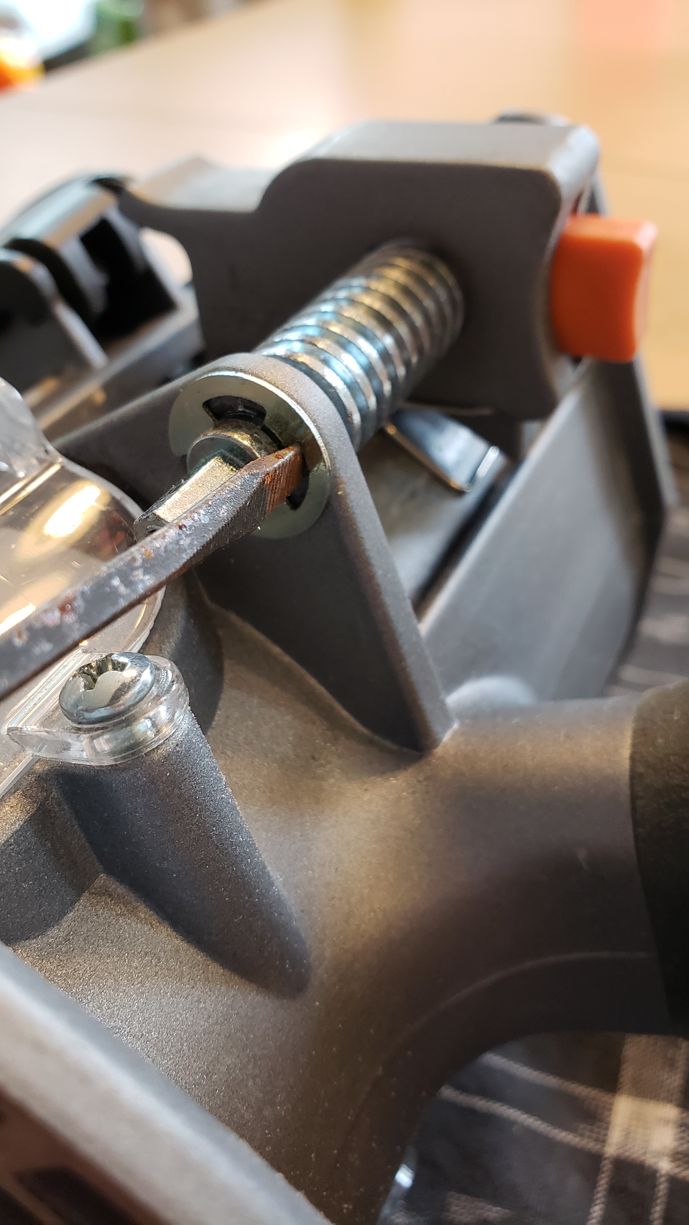
The top of the worm fits into a larger hole on the upper mounting. The bottom of the worm has a smaller diameter end which goes through a smaller lower hole and is secured by a C-clip on the other side.
Disassembly is easy - use a (preferably non-rusty) small screwdriver to pop the c-clip off. Put your free hand over the top so it doesn't go flying, and try not to stab yourself with a rusty screwdriver.
A 12-pc bag of 5/16-inch Hillman zinc washers from Lowes is $1.28. The barcode is 0 08236 59004 3, and my receipt shows a Lowes item number of 58125.
The washers fit around the non-threaded part of the worm. Placing one washer on the top of the lower mount and installing the worm presses it between the end of the threads on the worm and the lower mount. This puts the groove that holds the c-clip about 0.25mm inside the hole of the lower mount. This is enough to still get the c-clip in, but under pressure - leaving no room for travel in the worm.
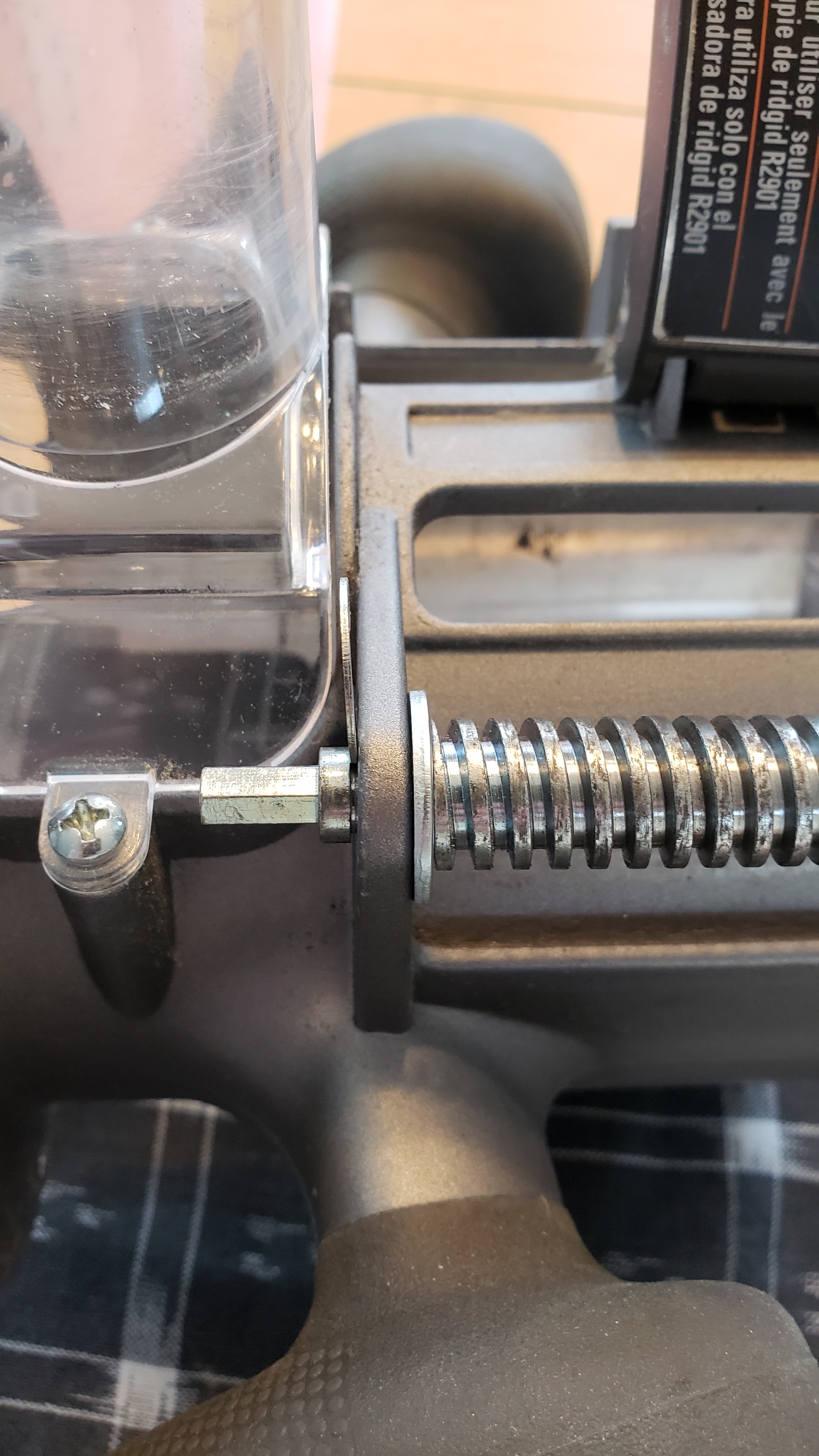
I chose to put the washer on the thread-side of the lower mount, because I didn't want to be pulling the threads into the lower mount for an extended amount of time as they're rotating. (I didn't want to make the threads "drill out" the lower mount)
PLAY IN THE WORM-SIDE (HOLE-SIDE, NOT TAB-SIDE) OF THE CLIP
The goal here is to keep the clip perpendicular to the worm and router body at all times. The easiest way to do so is to make the hole longer and have it fit the worm as closely as possible so the elongated hole can't tilt on the worm shaft.
The threads on the worm have a 1/2-inch diameter, and the clip has a 1/2-inch hole for it. The clip's hole has 1/8-inch of clearance all the way around its perimeter, making for a 3/4-inch area to work with.
A Hillman bronze machine bushing from Lowes is 1/2-inch long, has a 1/2-inch hole through the center, and has a 3/4-inch diameter flange on one side They come in packs of one for $3.91, and it has a Lowes item number of 1772.
Attaching this bushing to the side of the clip will extend the length of the hole from 5/8-inches to 1 1/8 inches, where the latter 1/2-inch of the hole doesn't have any other mechanisms to present any additional slop, like the clip does.
Do not attach the bushing to the lower (bit side) of the clip. If you do, it will hit the lower worm mount and not allow the router to extend its bit to the worm's fullest extent. This will likely prevent the bit from reaching more than 1/2-inch into the material. Since most material used is 3/4-inches thick, this wouldn't work.
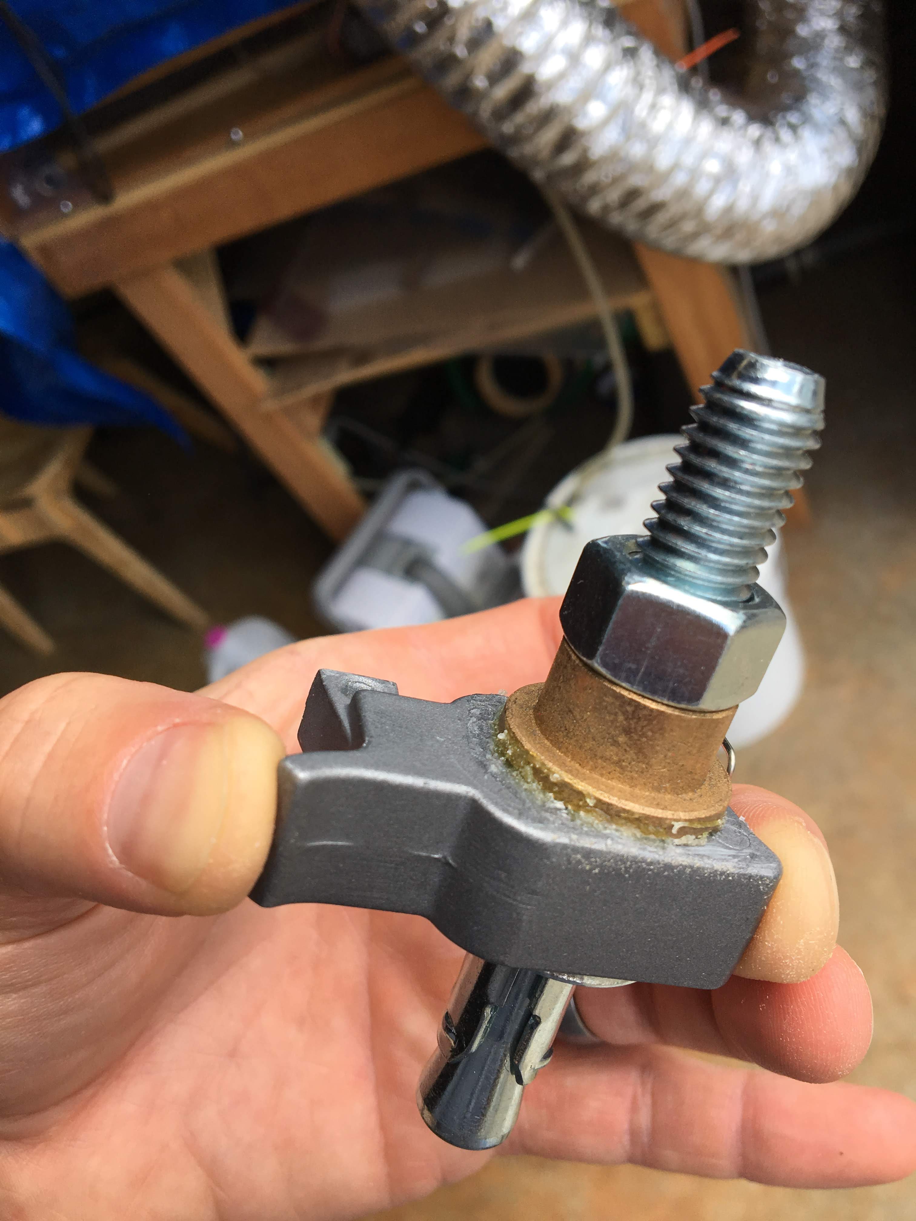
I carefully glued the bushing to the top (z-axis motor side) of the clip with Gorilla Glue, ensured it was aligned properly, and that an excess amount of glue hadn't seeped into the inside of the hole. Clamp the parts together and allow to dry overnight - Gorilla glue expands and there's no room for the bushing to be even slightly off-axis with the clip.
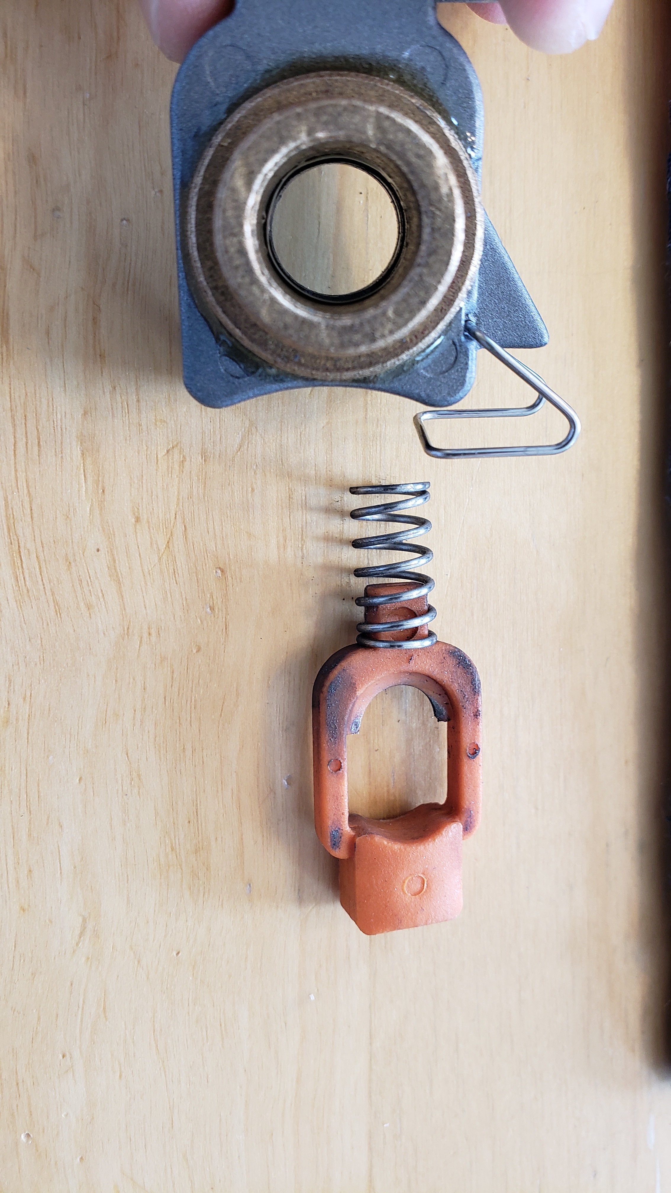
Don't leave the orange button and spring in like this while the glue dries. There's nothing good that can happen to it while the assembly is being glued and finished, wait until it's time to put the assembly back on the worm to reinsert the spring and orange button - you don't want it to get glued in place.
ChuckC had a spare 1/2 bolt and nut lying around, and because the clip has flat sides, this is an excellent way to keep the bushing and clip aligned while the glue dries. Just make sure it can be removed and you're not gluing the bolt inside of the clip, or you'll ruin a critical part of the z-axis assembly.
Gorilla glue will expand into the hole and harden. I waited for it to do so and drilled it out. I didn't have a 1/2-inch drill bit, so my 3/8-inch bit did fine. Make sure not to twist the bit in the hole assembly or you'll flange the hole out and make it looser on the worm shaft.
The clip has a small spring that presses its tab into the router's tab cutout. The spring is not designed to be strong, it's meant to be easily overwhelmed and allow the tab to pop out if the router is trying to jam into something too forcefully. (This is called a "mechanical fuse") The added drag of the longer hole on the shaft is something the spring struggles to overcome, and the clip can rotate on the worm unless the worm is oiled/greased to reduce the additional friction. This will rotate the tab out of the cutout and disengage the router body from the worm assembly.
Bending the body spring wider can make it push harder, or some people use rubber bands or bungee cords to keep the tab engaged in the router body cutout. I don't like either, because the tab moves up and down on the outside of the router housing, and the bungee cords / rubber bands are stationary. Research in progress
ADDITIONAL CONCERNS
TIGHTENING CLAMP ON ROUTER HOUSING
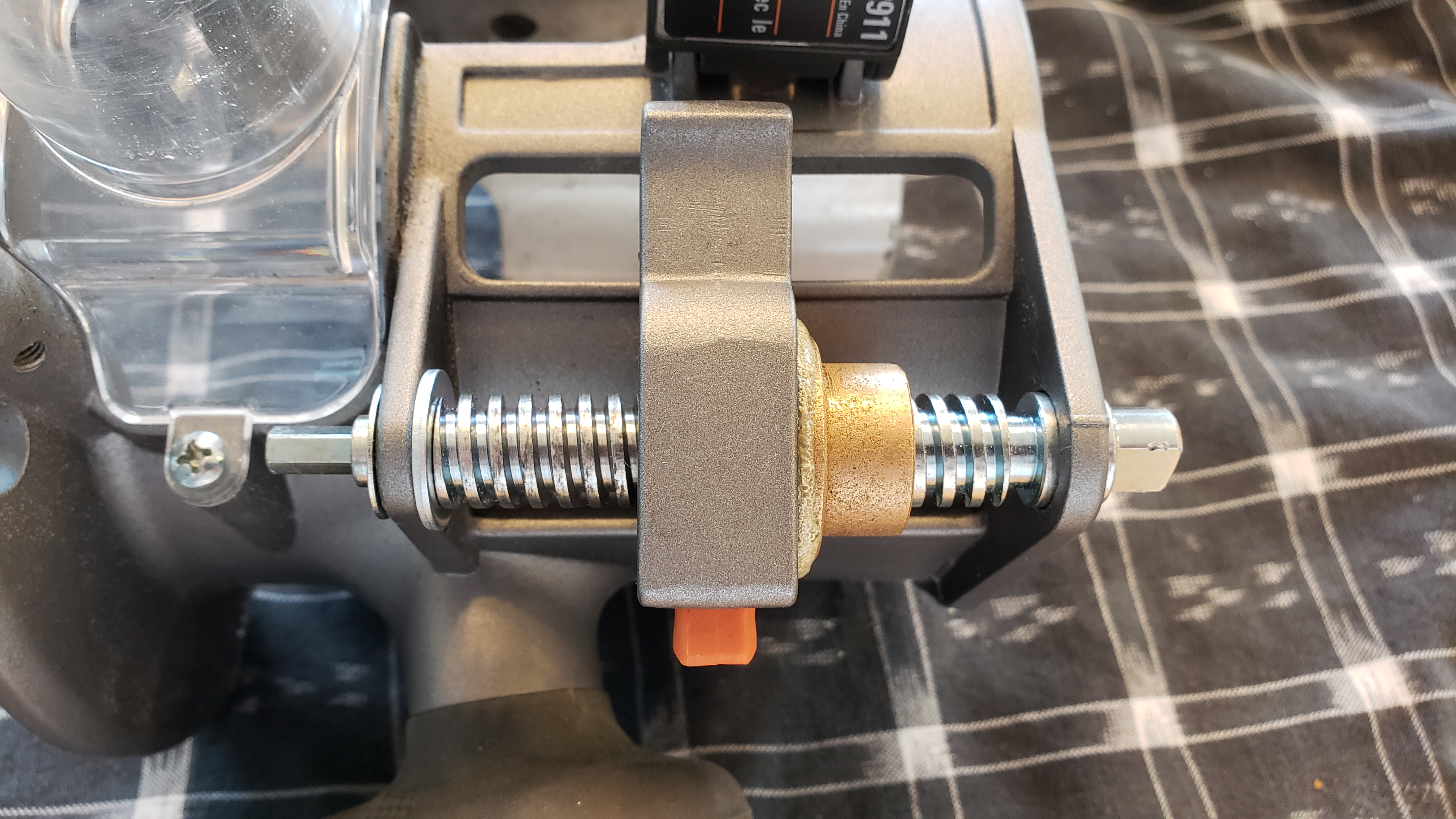
The router's sleeve has a clamp that's meant to hold the router body after it's been adjusted. The z-axis motor isn't strong enough to fight this when it's tightened to its factory settings - it's meant to hold the router body securely in the housing, which we don't want - it needs to slide. The clamp is seen top-right below.
Loosen the nut on the clamp bolt with a socket wrench, until the clip is very loose. Assemble the router, disengage the mechanical fuse (hold it out of the router cutout) and tighten the router housing enough so the router body can still slide up and down somewhat easily, but not so loose where the router body can tilt side-to-side inside the housing.
DRAG BETWEEN THE SLED AND PLYWOOD / ROUTER BODY AND HOUSING / MECHANICAL FUSE SPRING AND ROUTER HOUSING / WORM AND FUSE CLIP
Research in progress I'm waiting for some tough, slippery tape to put strips on both the sleeve and router body so it can slide better, but I suppose I could grease it as well.
The clip's tab is slightly smaller than the cutout in the router body. This leaves a tiny amount of play (<1mm for me) That's enough where I adjust the router for proper depth, and just set the traverse height to 5mm and let it be slightly off. Not sure how to remedy without compromising the function of the mechanical fuse.
Forums
Prerequisites
- Maslow CNC machine with motorized z-axis kit. This fix will work for routers without the kit, but is likely not necessary when a human is adjusting and checking the router at every depth change.
- Ridgid R22002 router. This fix may be needed and may work on other routers.
Parts List
1. One 5/16-inch washer
Lowes: Hillman 5/16-inch zinc washers, 12pc bag
UPC 008236590043, Lowes item number 58125
$1.28 as of 20MAY2018
2. One 1/2-inch machine bushing with 3/4-inch flange
Lowes: Hillman bronze machine bushing, 1pc.
Lowes item number 1772
$3.91 as of 20MAY2018