Yet Another Z-Axis Mod
Files
Edit this page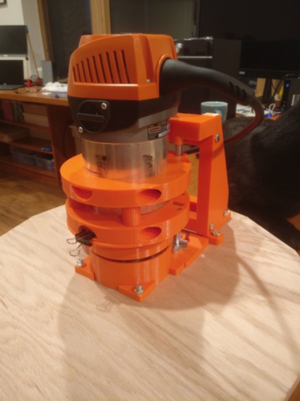 | Download FilesSource |
Yet Another Z-Axis Mod
I had gotten the z-axis kit with my Maslow originally, but I frequently found it off of spec when cutting. I tried all the simple fixes (bungee cord, gluing a bushing to the frame to keep alignment), and while they helped, I still had trouble with incomplete cuts way too often.
So I designed my own Z-axis kit that extends the stock solution, but doesn't rely on the Ridgid router's collar and it's not-intended-for-this-purpose mechanics.
The kit relies on the Z-axis motor from the original Maslow z-axis kit. Other than that all parts are 3D printed or listed in the BOM.
Additionally you will need the 3D printed parts from the forum and all the materials listed in the BOM.
Shout out to Gary D (@gder) for doing a lot of work beta testing and for contributing a bunch of ideas to the design. Thanks to Gary the design is a lot better than it would have been.
Instructions
Edit this pageAssembly
(IMPORTANT NOTE: There are now two alternate versions of the dust shroud and dust sleeve. If you have the ring kit or the original "L" brackets as your linkage system, then print the "standard" dust shroud and dust sleeve, which you will find in the main "Project Files" folder (v3dustshroud (use supports).stl and v3dustsleeve.stl). If you have a triangulation linkage kit (e.g. https://www.etsy.com/listing/558743441/maslow-triangulation-linkage-kit), you may need the alternate versions of the dust shroud (v3dustshroudalternateversion.stl) and dust sleeve (v3dustsleevealternateversion.stl). You'll find those parts in the "Individual Parts" sub-folder. Please be sure to plan out where your linkage system attaches and then decide which version you need before you start printing, as it takes upwards of 6 hours to print those models out.)
(NOTE: These instructions are available to download at https://github.com/MaslowCommunityGarden/Yet-Another-Z-Axis-Mod/raw/master/Build%20Instructions.pdf. Github is not honoring all of my markdown around bullets, so the online instructions are formatted a bit funky.)
- Print one set of all 3D printed parts. Where you need multiples of any given part, the provided STL files include the correct number of parts already. Some notes:
- PETG, ABS, or PLA should all be fine. I used PETG for mine.
- Default infill should be 20-25% or so, EXCEPT for the router body clamps (v3bodyclampbackhalfpair.stl & v3bodyclampfronthalfbraced_pair.stl). Print those with at least 50% infill for clamping strength.
- You should not require supports on any parts EXCEPT the dust shroud (v3dustshroud (use supports).stl). Supports will be necessary unless you have a very dialed-in printer.
- Some post-printing cleanup may be required, especially on:
- The slots where M3 square nuts slide in
- The alignment pegs at the bottom of the rods base (v3rodsbase.stl) and the dust shroud (v3dustshroud (use supports).stl)
- Cut a sled blank. I cut mine on a table saw out of some scrap plywood; just find a way to cut a ~17" roughly-circular blank.

- Mark the center on your sled blank and cut a 2 - 2.5" hole as close to center as possible.

- Find the "rods base" (v3rodsbase.stl) in your 3D printed part set and position it so the snap-off "bullseye" is centered on the hole you just cut.

- (NOTE: You can proceed to mark all the holes at one time and then drill them in a following step, or you can mark-drill, mark-drill. The latter is probably more accurate, but I did all my marking in one step, so that's how I talk it through here.)
- Dry-fit the dust shroud (v3dustshroud (use supports).stl) to the rods base using the alignment pegs at the base. (Note, make sure you've cleaned up the pegs of any printing artifacts so you get a nice snug fit; if the pegs don't slide in all the way clean them up some more.)
- Assemble all parts of the motor brace assembly (v3motorbraceassemblyall.stl). It should be self-explanatory enough how to assemble, and the result should look like the following photos. Just remember that you'll need 6 M6 bolts (35mm long to 50mm long) and 6 M6 square nuts to attach the cross-members.
- Dry-fit the motor brace assembly to the rods base (there are two alignment pegs at the base to ensure alignment. Remember to clean the pegs & holes up for a snug fit if needed.)
- Now that you have all the parts that mount directly to the sled dry-fit, confirm the placement of the bullseye and mark all of the holes for drilling. Note:
- There are six holes in the rods base
- There are four holes in the motor brace assembly
- There are two holes in the dust shroud
- If you don't have another way to countersink, you can turn your router back into a hand-held router temporarily and use it to router out the countersink holes you need.

- Drill and countersink (from below) all the holes you marked.
- Once you've drilled all of your holes, you can remove the bullseye from the rods base. Just use an X-acto knife or similar to snip it off close to the base:
- Now mount the two rail support blocks (left and right sides) and the pillow block (center) in the rods base and tighten them down fully. Some notes:
- Make sure to come up from below with your bolts.
- The pillow-block (center) uses M5 bolts. The rail support blocks take M6 bolts.
- The rail support blocks have a slot that is there to make it easier to tighten the lock screw.
- Mount the lead screw in the pillow block (in center). It uses two set screws to hold the lead screw fast. (Note: on mine, the lead screw has a little wobble even when properly secured. It'll all firm up when it's fully assembled.)
- Mount the linear rails in the rail support blocks and tighten the set screws.

- Now add the motor brace assembly and bolt it down fully from below.
- Ditto the dust shroud. It should look like this when partially assembled:

- Now prepare the router clamp as follows:
- There are four parts to the router clamp, two per STL file (v3bodyclampbackhalfpair.stl & v3bodyclampfronthalfbraced_pair.stl).
- The two parts of the "lower half" join together with the cylindrical pegs, one to the other. Join them together now. (They will probably never come apart once joined, but if you want to be extra safe, put some CA glue in the holes before you join them.) (Note: ignore that in the photo both halves have that smiley-face cutout; yours will only have that on the "bottom" piece.)

- The two parts of the "upper" half don't physically join, but you will install them bearing-holder to bearing-holder.
- Insert the four 8UU bearings in the bearing holders in the "upper" halves and tighten down with M3x8mm screws and square nuts.
- Insert the lead-screw trapezoidal nut in the bottom piece of the "upper" half (the one with four additional M3 holes in it for bolting on the dust sleeve). This requires 4 M3x25mm screws and nuts.
- Use four M3x20mm screws and nuts to bolt the top half of the dust sleeve onto the bottom of the upper-half bottom:


- Finally, insert two M3 square nuts in the bottom piece of the lower-half and place two 8mm M3 screws in them. There are two slots on the ends of the bottom piece to accept the nuts. (Note they will not screw all the way in; they are designed to stick out about 2 mm or so for cleating the dust sleeve.)

- It's best if you try to get the cleating screws at about the right depth now; to do that, fit the bottom half of the dust sleeve (v3dustsleeve.stl) on the bottom of the clamp piece, and screw the screw in snugly, then back it off 1/2 turn. Now remove the dust sleeve, it goes on only when operating the rig.

- Install the upper half of the router clamp:
- Place the "bottom" piece (the one with the dust sleeve attached) on the rails. Some notes:
a. Be gentle, if you come in at too much of an angle, you can force ball bearings out of your linear bearing.
a. You might have to gently straighten out the tops of the linear rods to seat the bearings correctly.
a. Once you have the bearings on, you will need to push down a little to get the trapezoidal nut to engage the lead screw.
a. Once the lead screw is engaged, you can move the clamp up and down by turning the lead screw manually.
a.
 a. Now place the other top-half piece, making sure to flip it so the bearing holders are touching each other, as shown.
a.
a. Now place the other top-half piece, making sure to flip it so the bearing holders are touching each other, as shown.
a. 
- Place the "bottom" piece (the one with the dust sleeve attached) on the rails. Some notes:
a. Be gentle, if you come in at too much of an angle, you can force ball bearings out of your linear bearing.
a. You might have to gently straighten out the tops of the linear rods to seat the bearings correctly.
a. Once you have the bearings on, you will need to push down a little to get the trapezoidal nut to engage the lead screw.
a. Once the lead screw is engaged, you can move the clamp up and down by turning the lead screw manually.
a.
- Assemble the Axis Cap:
- Find the 3D printed part for the Axis Cap (v3axiscap.stl)
- Insert two M3x8mm screws and square nuts in the rod holders. (If you don't use square nuts, you will have to hold the nuts with needlenose pliers when tightening them.) Leave these loose / not fully tightened.

- You do not need to install square nuts in the slots in the top of the axis cap; that's a remnant of a previous design iteration.

- Now use 6 M3x6mm screws to mount the motor from your stock kit. Note the motor shaft should be towards the open side of the axis cap, as shown:

- Mount the Axis Cap:
- Find your coupler (from the BOM, not from the stock kit) and slide it on the lead screw. Do not tighten yet.

- Gently place the axis cap on top of the linear rails and slide the motor shaft into the coupler, as shown:

- Now attach the coupler onto the motor shaft and lead screw using the set screws. Some notes on this:
- Slide the coupler up a bit to preserve your full range of motion. But not so high it will grind against the motor screws when in operation.
- The upper set screw tightens against the flat side of the motor shaft.
- You may need to connect your motor to GroundControl (GC) to get the shaft oriented so you can access the flat side. Use small moves to get the shaft in the correct position.
- Once you have the coupler fixed to the motor, use the lower set screw to clamp it to the lead screw.
- Following this, find the other two set screws and tighten them down as well; this will make sure everything is tight and secure. (Again, you may need to use GC to orient the shaft to permit you access.)
- Finally, tighten those M3 screws that secure the linear rods into the rod holders underneath the axis cap.

- Bolt the Axis Cap to the Motor Brace Assembly using two 8Mx35mm bolts and two M8 square nuts. You will need to hold the square nuts in place from underneath--the slots for them are on the bottom face of the Axis Cap.
- Place the Router
- Now it's time to place the router. Lay it into the groove created by the two top-half clamps with the front of the router facing towards the hose coupler.
- If you had previously greased your router body, as is recommended for the stock kit, clean that grease off before placing it. We don't need it slipping inside the clamp.
- Leave about an inch or so of the router body visible below the bottom-most part of the clamp. (You can fine-tune the placement later if you find you have too much or too little vertical range.)
- The braced-pair "lower" half of the router clamp needs to be mounted to hold it in place. Be sure you place the lower half correctly: with the "smiley" hole and the cleat-screws closer to the sled.
- Use 4 M8x35mm bolts and M8 square nuts to secure the lower half of the clamp. It can be a bit tricky to place the nuts, hold the router, and screw things together. It's a bit easier if you flip the whole rig on its back on a table.
- It's not horribly important that you have your router precisely facing the hose opening, but get it as close to that as possible. If you mount it wrong, the power cord and back part of the router can make contact with the axis cap and cause runtime issues.
- Don't tighten the M8 bolts right away, just make them snug at first. Then check the router's placement and orientation and tighten things down.
- When tightening, alternate between the left-side and right-side bolts, using small (e.g. 1/4 turn) turns. This makes sure you don't stress one side of the clamp too much.
- Here's where you find out if you printed the router clamp with enough infill. Less than 50% infill and it's liable to crack when you try to tighten it down fully.


Pre-flight and Usage
- Before attempting any moves in GC, be sure to modify your GC configuration. Find the setting for Z-axis pitch, and put the appropriate setting for your lead screw. If you bought the kit I linked in the BOM, that value should be 8mm.
- NOTE that this kit does not have an end-stop, so you can tell GC to crash the nut into the coupler or the pillow-block at bottom. Be cautious in your moves, and be ready to hit the "Stop!" button in GC if you've mistakenly told GC to lower / raise beyond the limits.
- Test your kit by moving your new z axis up and down (in small increments at first).
- Prior to actually doing any cutting, be sure to define "zero" on your newly-installed Z axis kit.
- The dust sleeve is designed to go on and come off easily so you can access the collet and change bits. To place it initially:
- Slide the back into the cleating screws you placed in the bottom of the body clamp:

- Once the sleeve is fully engaged on the cleating screws, place a medium-size binder clip at the front clip-point (the smiley-shaped opening):

- To access your collet and change bits and zero your router:
- Remove the binder clip and remove the front part of the dust sleeve
- Raise your router to maximum height so it clears the dust shroud
- You should be able to access the collet lock from behind, and get a wrench into the opening where the dust sleeve had been.
Forums
Bill of Materials (BOM)
- Wood for the sled.
- Linear Motion kit (or equivalent). You'll either need a linear-rod kit like this one. or equivalent parts. If you decide to source the parts yourself instead, here's what you really need from that kit:
- 2x 8mm x 150mm smooth rails
- 1x 8mm x 150mm lead screw
- 4x LM 8UU bearings (the kit has these embedded inside linear slide blocks, but they pop out easily if you remove the retaining clip)
- 1x 8mm lead-screw nut
- 2x 42x24x10mm 8mm rail support block
- 1x 48x12x27mm 8mm pillow block bearing
- (You do not need the shaft couplers, plus there is an extra pillow block, and 2 extra rail support blocks)
- One 6mm to 8mm shaft coupler, like this one.
- An assortment of M3 screws & nuts.
- Additionally you will need 4 M3x25mm screws
- You will also need some square M3 nuts, as well as some M6 and M8 ones. Probably best to get a kit like this one.
- 4x M8 x 30mm hex screws (phillips head or "button" style [that accepts a hex driver]).
- 2x M8 x 35mm hex screws
- 6x M6 x 35mm (up to 50mm) screws for the motor-assembly cross-braces
- Some M6 x 20mm screws and nuts and M5 x 15mm screws with nuts for mounting parts to the sled
- (Note: I got all of the M8/M6/M5 screws I needed by buying a TV mounting kit like this one.)