Maslow Electronics
Files
Edit this page | Download FilesSource |
Maslow Electronics
The printed circuit board which powers the Maslow CNC Machine
======================
Layout
Schematic
Instructions
Edit this pageMaslow Electronics Setup
We've done our best to keep the electronics for Maslow as simple as possible.
Step 1: Identifying Parts
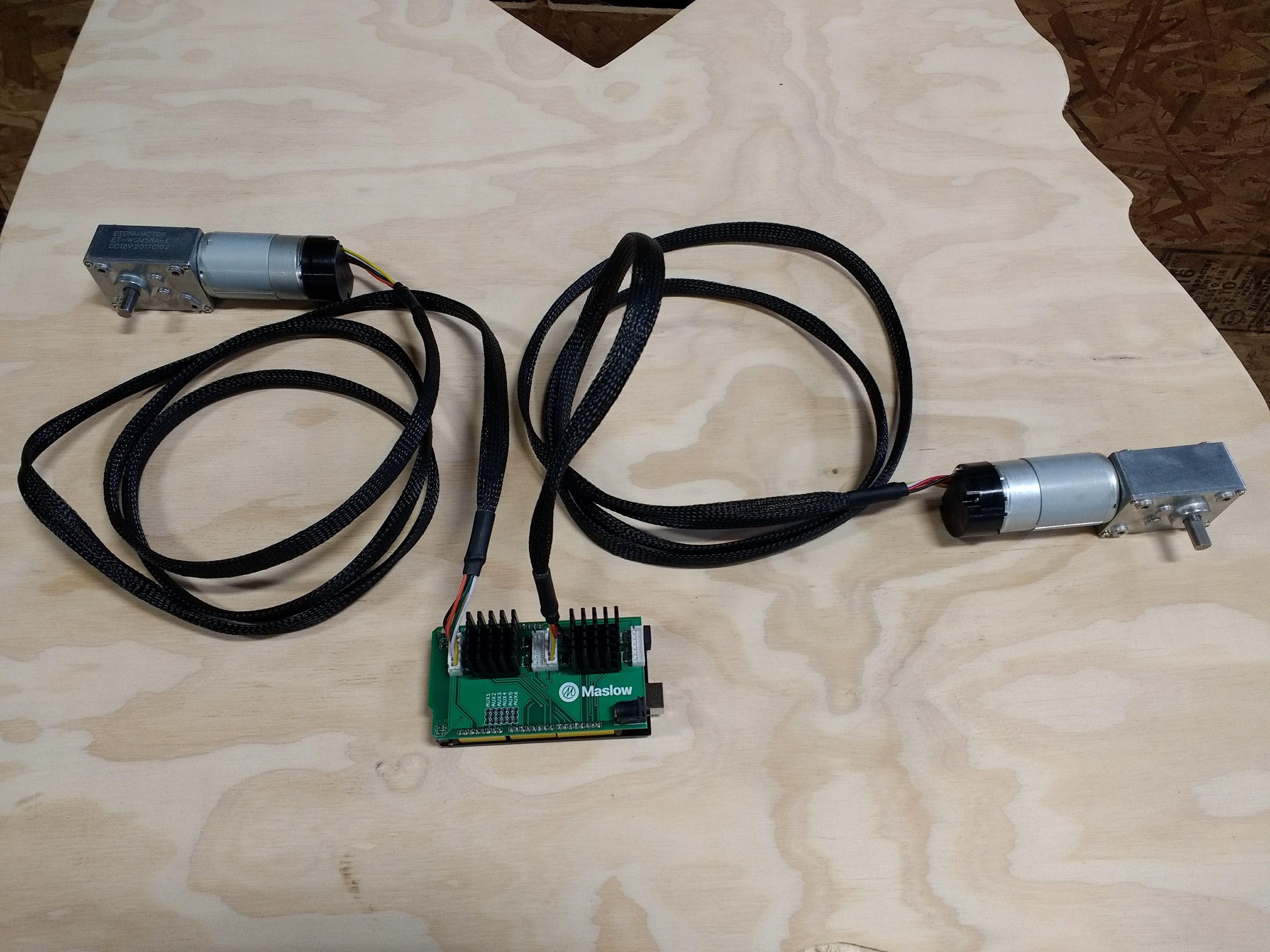
There are five pieces to the Maslow electronics system. Shown in the picture below from left to right and top to bottom they are:
1. The Motor/Encoder/Gear Box Units
2. Motor Wires
3. Maslow CNC motor controller shield
4. Keystudio Mega 2560 microcontroller (Arduino compatible) with USB Cable
5. 12V DC 5A / 110-250V AC Power Supply
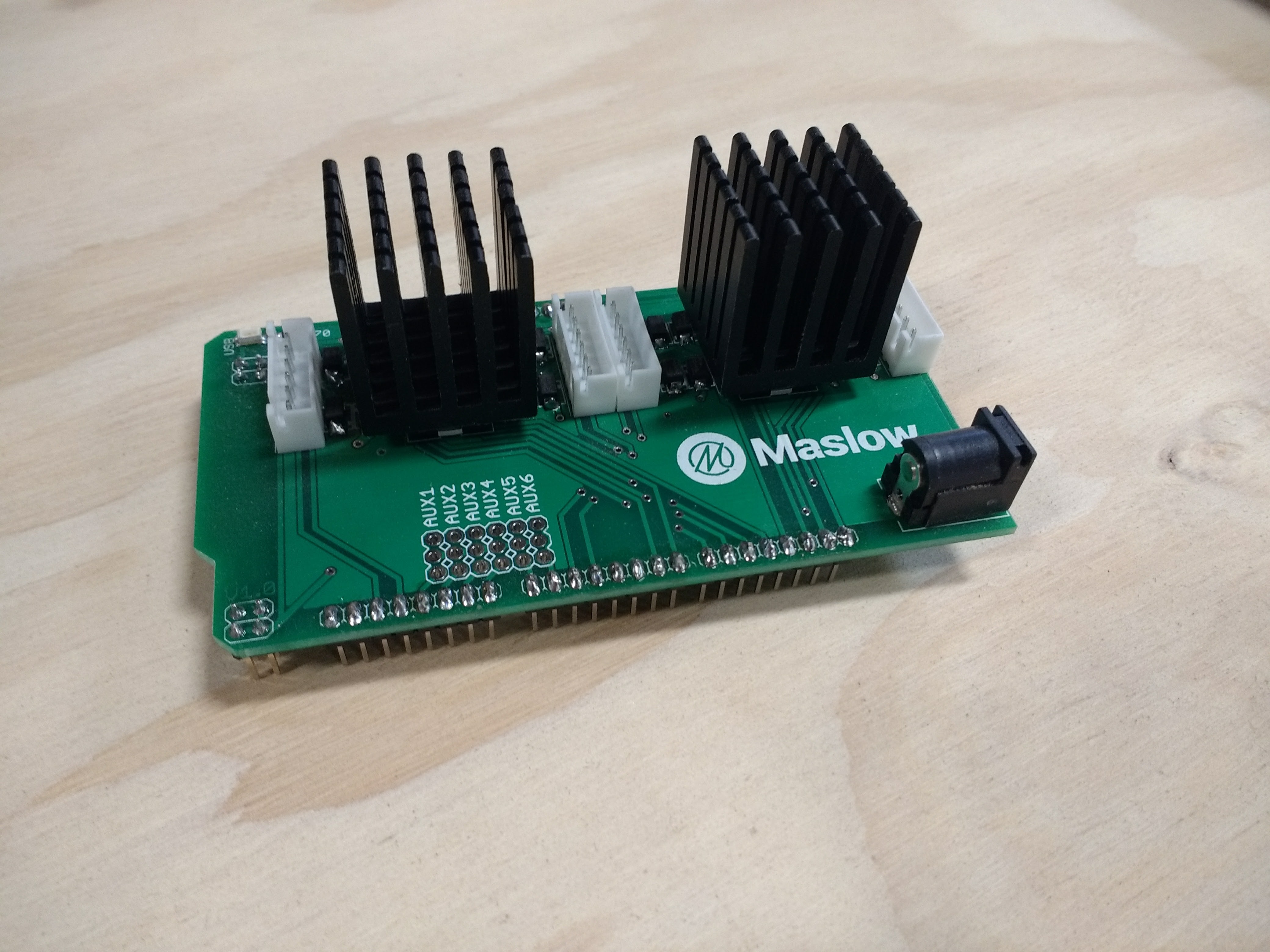
Step 2: Attach Heatsinks
Attach the sticky backed heat sinks found in your hardware bag to the motor controller shield. (Note orientation of heatsinks)
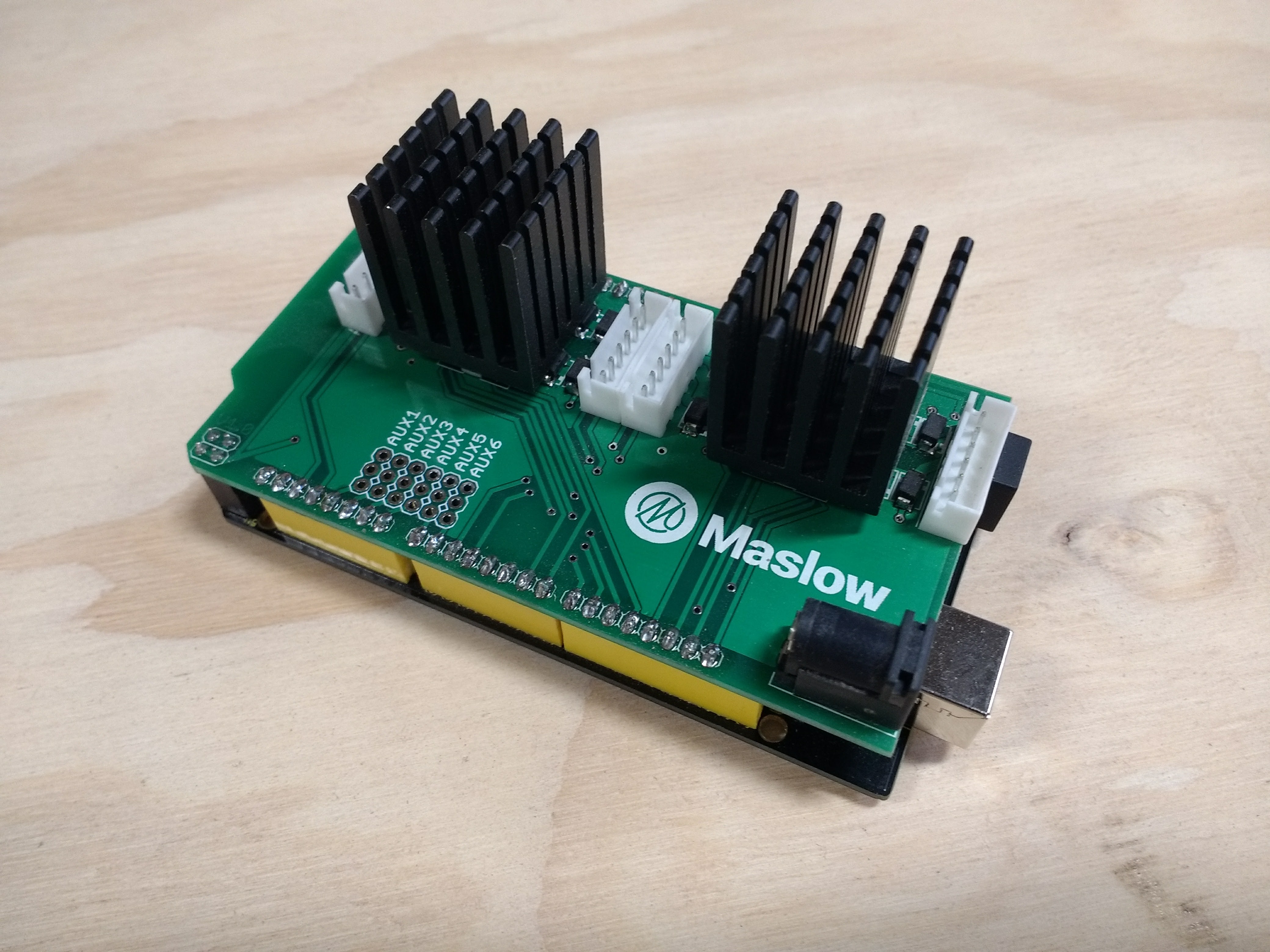
Step 3: Connect Arduino Shield
Attach the Arduino shield onto the Keystudio Mega 2560 microcontroller. Make sure all the pins are not twisted and that are aligned with the microcontroller before pushing the motor controller shield.
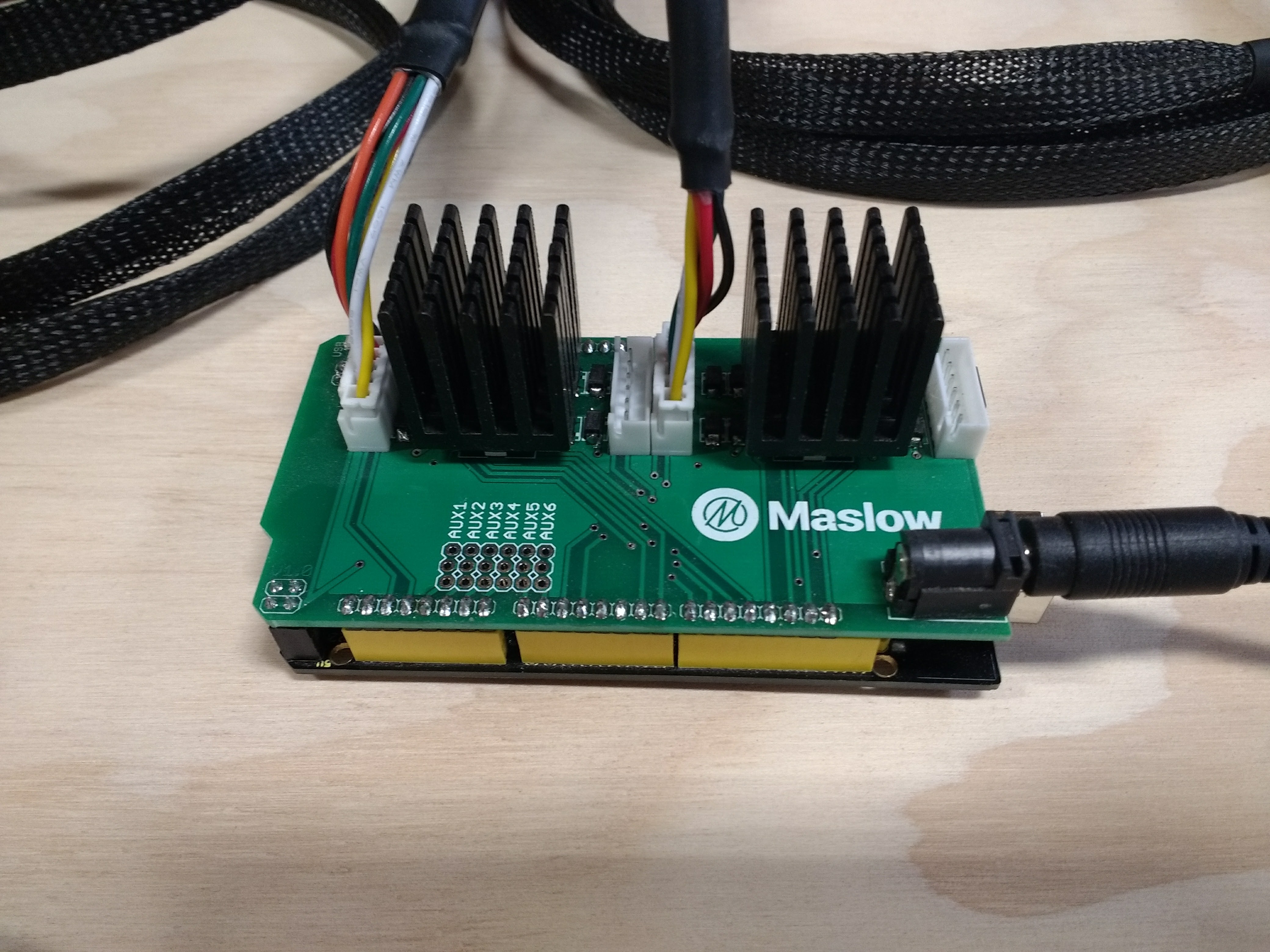
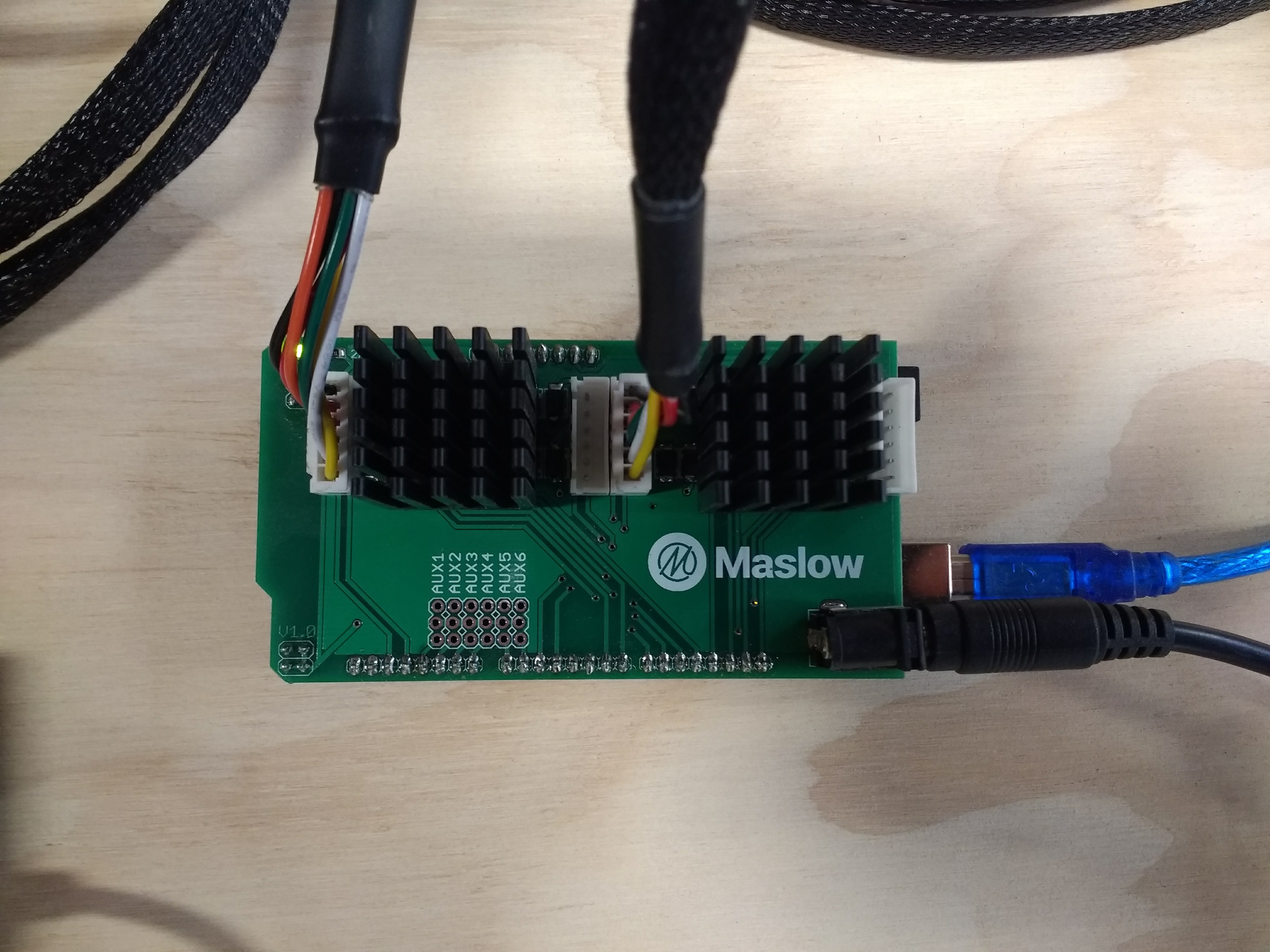
Step 4: Connect The Motors
Attach the motors to the motor controller shield. Note that the motors connect to ports 1 and 3 not 1 and 2. This is to better distribute the motor power draw across both motor driver chips. Port 3 controls the left motor and Port 1 the right motor (as viewed when facing the MaslowCNC). The cables have two sides, so make sure that when plugged in the Arduino shield, the yellow wire is at the bottom in both ports as seen in the following photo. When using the optional Z axis, this motor is connected to port 2.
Step 5: Connect The Power Supply
Plug the 12V power supply into the motor controller shield. Note that the power supply plugs into the motor controller shield and not to the microcontroller. Plugging the power supply into the Arduino will not damage it, but it also will not provide power to the motors. We chose the most common power supply plug to make replacements easy to find, unfortunately because it is so common this is also the same power supply plug that the Arduino uses, which is somewhat confusing.
Step 6: Connect The USB Cord
Plug the USB cord into the Arduino and into your computer. Note that the "USB" light will come on to indicate that the board is connected and receiving power from your computer.
Step 7: Proceed
You have finished setting up the Maslow electronics system. Proceed to the next step and install the open source Maslow Firmware on your Arduino.
Forums
PCB BOM
All of the part numbers below are digikey parts unless otherwise stated.
| Part | Part # | Number Needed | # In Schematic |
|---|---|---|---|
| XH-Series Connectors | 455-2271-ND | 3 | J1-3 |
| Power Jack | CP-202BH-ND | 1 | J4 |
| 1x8 .1" headers | 732-5321-ND | 4 | J5-8 |
| 2x2 .1" headers | 952-2119-ND | 2 | J9,10 |
| Flyback Diodes | MRA4004T3GOSCT-ND | 12 | D1-12 |
| .1uF Filter Caps | 311-1361-1-ND | 4 | C1-4 |
| 1uF Filter Caps | 445-5146-1-ND | 2 | C5,6 |
| H-Bridge | 497-3624-1-ND | 2 | IC-1,2 |
| Indicator LED | 475-1410-1-ND | 2 | LED 1-2 |
| Current Limiting R1 | RMCF0805JT270RCT-ND | 1 | R1 |
| Current Limiting R2 | 541-4162-1-ND | 1 | R2 |
| 23x23mm heatsink | Mouser-532-374124B35G | 2 | N/A |