The Default Frame
Files
Edit this page | Download FilesSource |
The Default Frame
The default Maslow CNC frame
This frame was designed as the result of a massive community collaboration. It is designed to replace the old default frame. It is designed to be built anywhere in the world so the dimensions of the lumber are not critical, and no hardware is needed other than screws and glue.
The forum thread which discusses the design process can be found here. While 53 people contributed, @dlang and @madgrizzle deserve the bulk of the credit.
The OnShape model for the CAD design can be found here: OnShape
Instructions
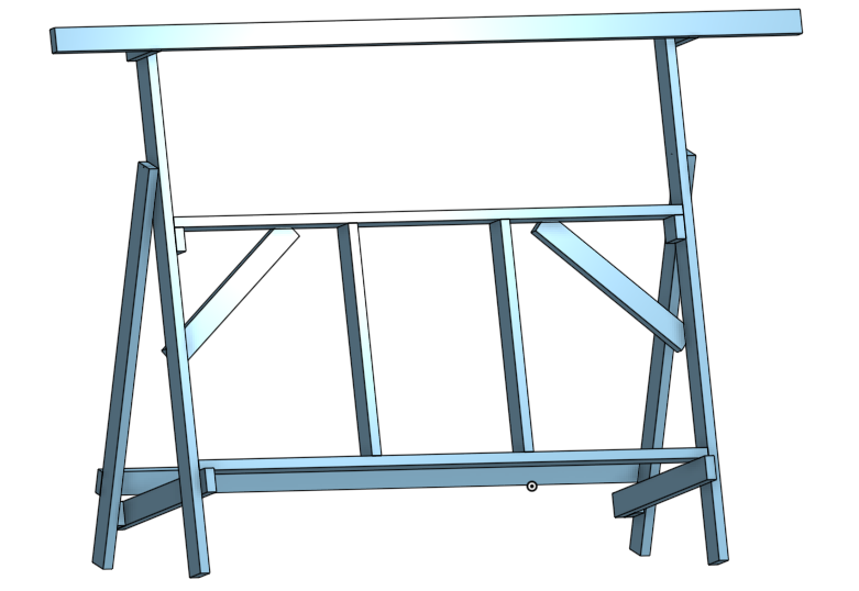
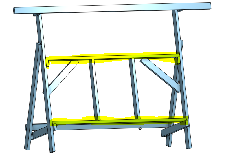
Edit this pageThe completed machine will look like this:
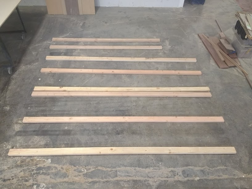
Step 1: Buy Materials
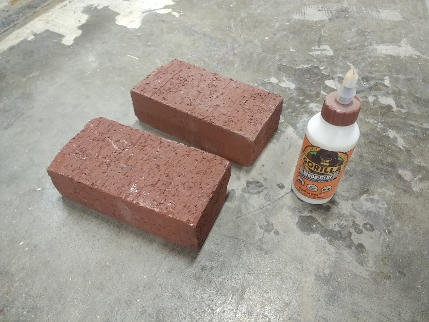
To put together this frame you will need: * Six 10' 2x4s * Two 8' 2x4s * Two sheets of 3/4 Plywood * Two bricks * Wood glue
Find wood screws in the Maslow kit
- 2-1/4 screws included in kit.
The dimensions of the lumber are not critical, so if 2x4s are not available in your area, the equivalent lumber will work.
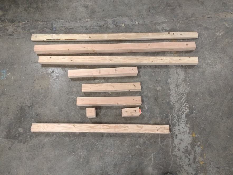
Step 2: Cut the 2x4s
Cut your 2x4s as shown in the picture below. None of these cuts are of a critical length. Small errors in the lengths of any of these parts will not affect the accuracy of the machine. Do try to create square ends as much as possible.
You will want to choose your straightest ten foot 2x4 to be the top beam.
It can help to label the parts as you cut them.

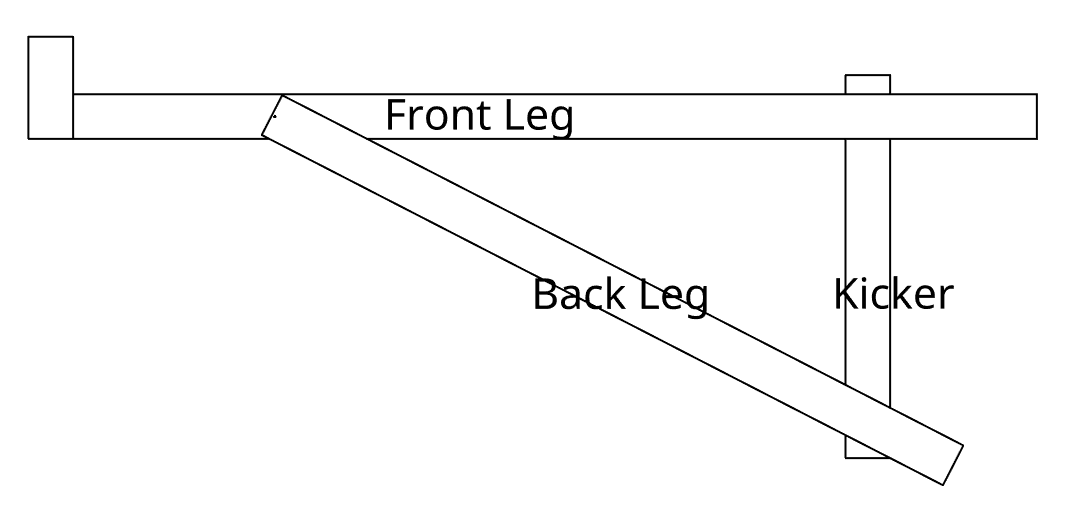
Step 3: Assemble the left leg
To put together the left leg we will need:
- one Spacer
- one Front Leg
- one Kicker
- one Back Leg
The default frame is designed to use a combination of glue and screws to hold it together. The screws hold the parts in place while the glue dries and the glue will provide a very rigid connection once it dries.
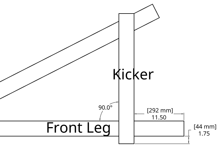
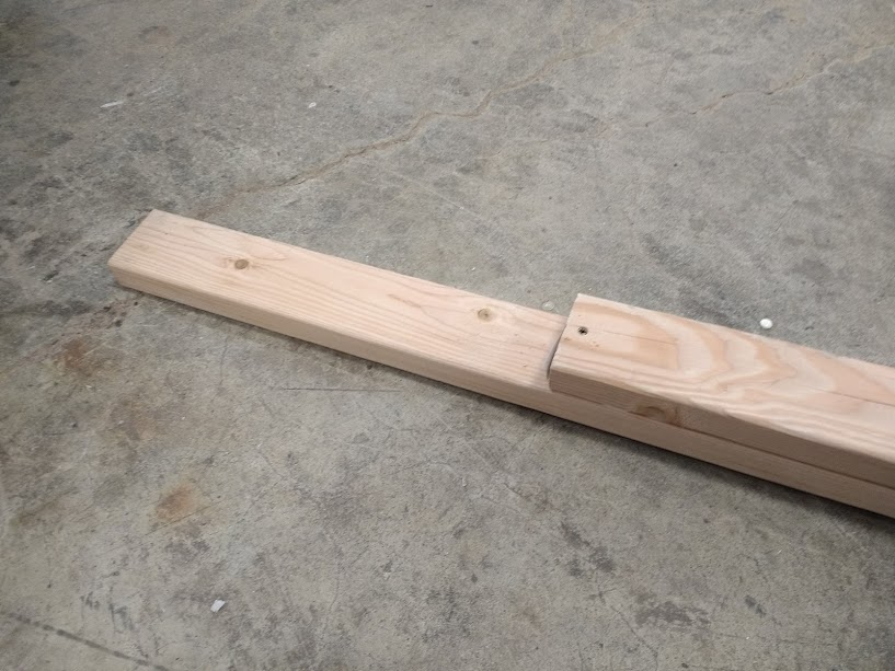
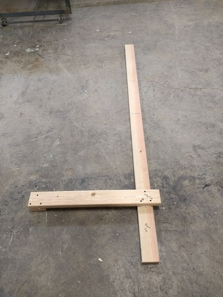
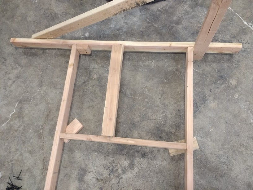
First we will attach the kicker to the front leg. It should be positioned 11.5 inches (290mm) from the bottom of the front leg and protrude past the front leg by 1.75 inches (45mm). This is one of the few connections in this design which requires some care and measuring so take your time.
Place the spacer under the other end of the kicker to hold everything level.
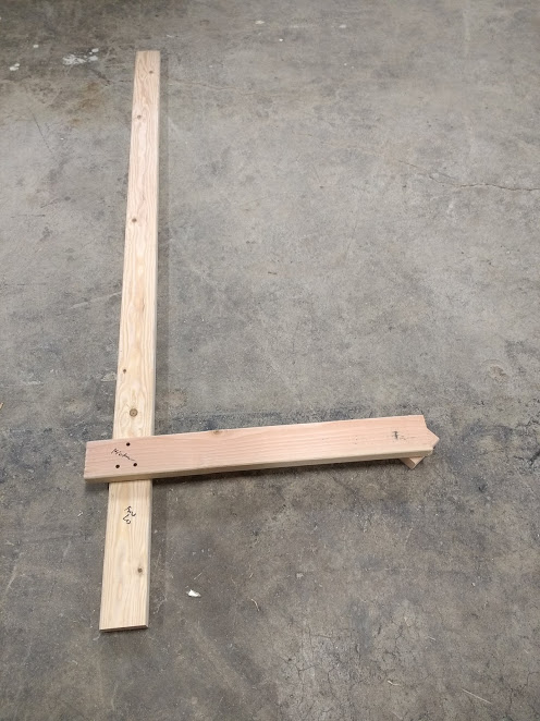
Next, screw the spacer in place under the other end of the kicker.
![]()
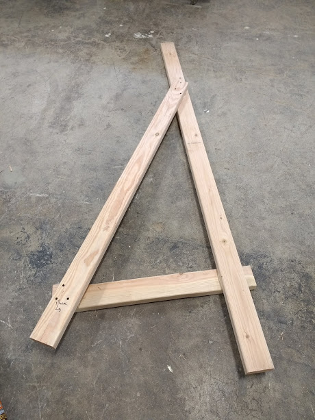
Flip the entire assembly over and we will attach the back leg.
To position the back leg in the right location, we're going to put it on top of the front leg, then rotate it into position.
Place the back leg on top of the front leg with their bottom edges aligned.
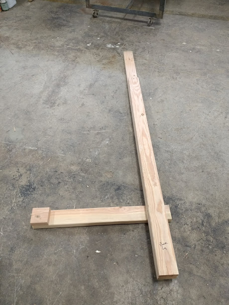
Put one screw through the top of back leg into the front leg.
Then, using that screw as a pivot point rotate the back leg out until it intersects with the lower edge of the kicker.
Screw and glue both sides, and you are all done with the left leg.
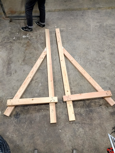
Step 4: Assemble the right leg
Repeat that process for the right leg keeping in mind that it is the mirror image.
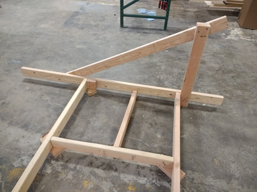
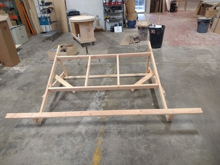
Step 5: Attach the front crossmembers
In this step we will be adding the the two front crossmembers.
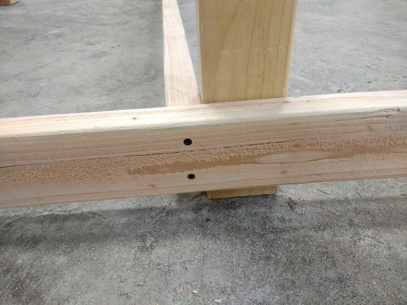
First place the lower crossmember so that it rests on the kicker and screw the crossmember into place by screwing through the crossmember into the kicker. Using some scrap blocks to keep everything in place can help here.

Then attach the crossmember further by screwing through the front leg and into the crossmember from the side.
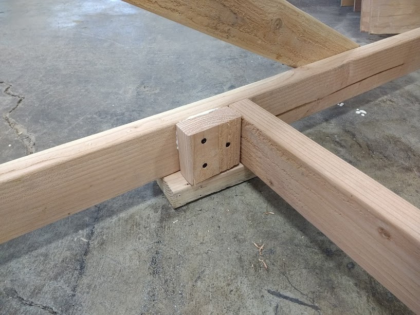
Next, use the verticals to measure the spacing between the lower and upper crossmember and when the distance is right screw the block in place on either side, then screw the crossmember into place.
Step 6: Attach verticals
Place the two verticals between the upper and lower crossmembers. One of the diagonal pieces can be used as a measuring tool to make sure they are even and parallel. Screw through the crossmember into the vertical.
Step 7: Attach diagonal bracing
Attach the diagonal bracing.

Step 8: Attach rear crossmember
Attach the rear crossmember.

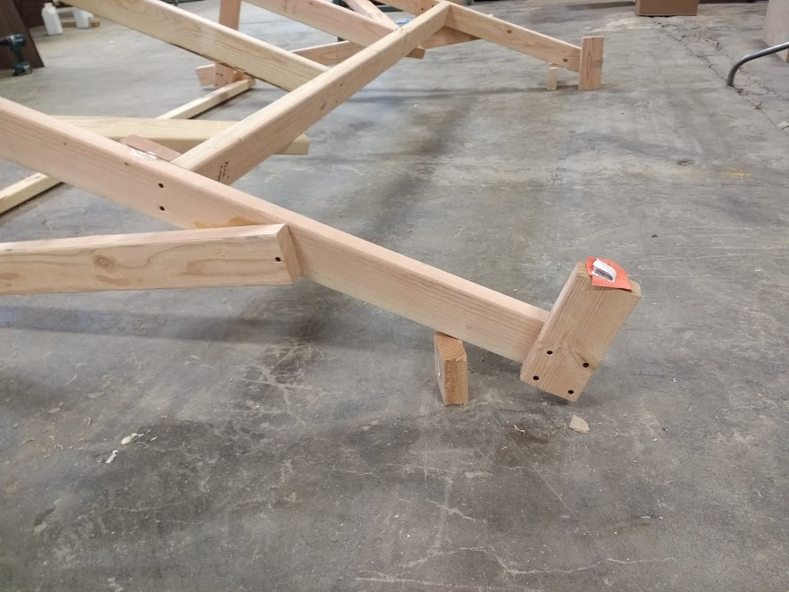
Step 9: Attach beams
Next we need to add the two beams which will hold the top bar. This is the second place where an angle is critical. These beams were positioned on the cut list so that they will have one square factory end, this end should be out so that the top bar can attach to it. The beams meet the legs at a 90 degree angle.
Step 10: Attach top bar
Attach the top bar by screwing through it and into the two beams.
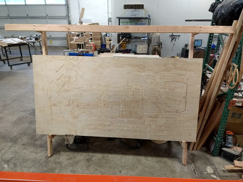
Step 11: Stand up the frame and attach plywood
Stand up the frame and attach the sheet of plywood which will makeup the back of the machine. Attach the plywood using a few screws near the edges of the plywood. It is not structural and having too many screws especially in the center of the sheet increases the odds of hitting one accidentally while cutting.
Congratulations! You've built the mechanical part of your machine. Now it's time to attach the electronics.
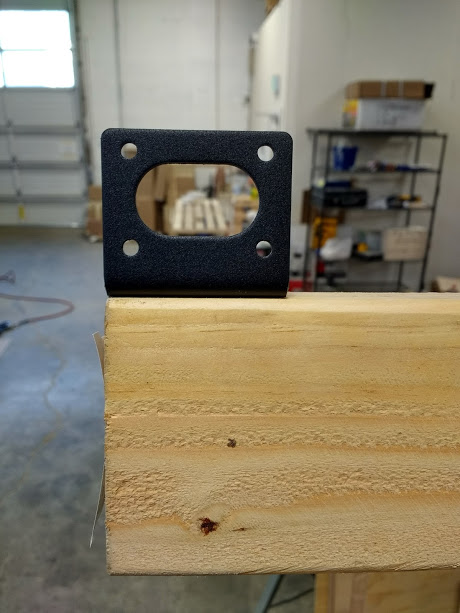
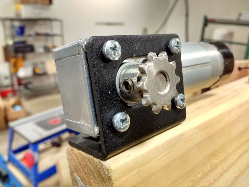
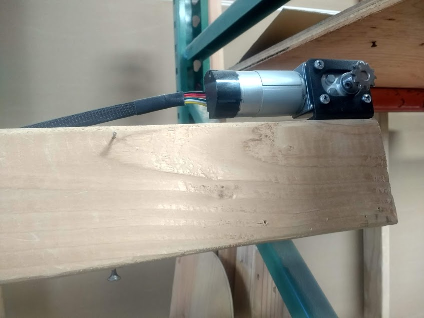
Step 12: Attach the motors
Screw the motor mounting brackets to the ends of the beam flush with the front edge using four of the short wood screws.
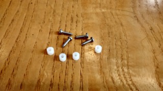
Attach the motors using the small screws and lock washers.

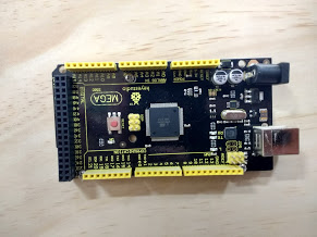
Step 13: Attach the Arduino and electronics
Attach the Arduino to the back of the plywood using the small screws and standoffs, then reconnect the electronics. If you would like to reference them, the instructions for connecting the electronics are here.
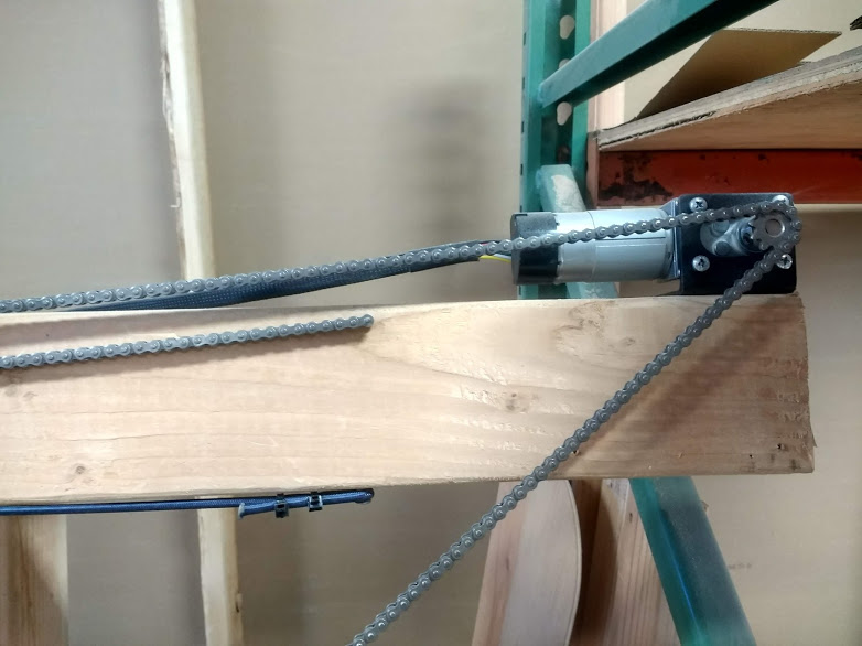
Step 14: Install chain hardware
Attach the two sprockets using the included set screw and Allen wrench.
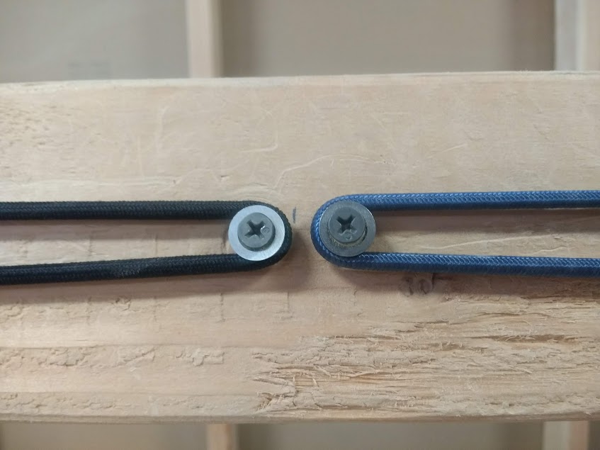
Mark the middle of the top beam and install the two pulleys for the cable system just to either side of the center.
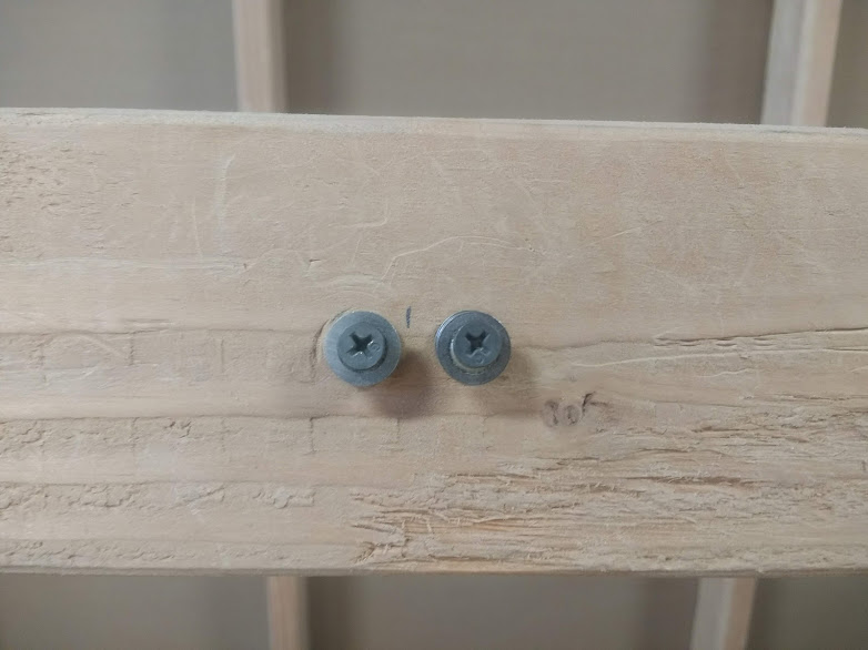
Place a screw in the top beam just to the inside of the motor and on the front of the top beam hammer in one of the small nails in the hardware bag leaving a little more than 1/4 inch protruding. The nail should be placed about 200mm or 8 inches from the end of the board. The chain will attach to this nail.
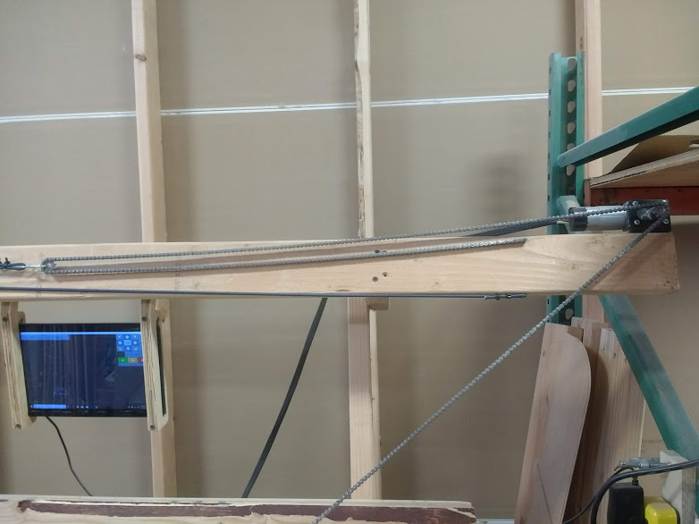
Step 15: Hook up the chain
Take the chain and loop it over the sprocket leaving the outside end dangling. Hook the inside end of the chain on the small nail. Take the stretchy cord and form a loop in each end using zip ties and hook the end over the screw to the inside of the motor. Place the idler sprocket and S hook in the loop of the chain, then pass the loop end of the stretchy cord around the pulley and hook it to the S hook.

Now that we have completed building the frame we need to use it to cut the sled. Instructions to build a temporary sled and use it to cut the final version can be found here.
Forums
To put together this frame you will need:
Six 10' 2x4s
Two 8' 2x4s
Two sheets of 3/4 Plywood
Two bricks
Wood glue
The dimensions of the lumber are not critical, so if 2x4s are not available in your area, the equivalent lumber will work.